Grid voltage generating circuit

A voltage generation circuit, gate voltage technology, used in electrical components, electronic switches, pulse technology, etc.

Inactive Publication Date: 2014-10-22
ADVANCED POWER ELECTRONICS CORP
View PDF5 Cites 6 Cited by
  • Summary
  • Abstract
  • Description
  • Claims
  • Application Information

AI Technical Summary

Problems solved by technology

[0003] However, the use of a charge pump circuit requires a specific charging time to reach the voltage required to turn on the transistor switch. For electrical devices that require fast startup, this charging time becomes the bottleneck of whether the electrical device can achieve instant use.

Method used


Image

  • Grid voltage generating circuit
  • Grid voltage generating circuit

Examples


Embodiment Construction

[0010] The following is a detailed description of preferred embodiments of the present invention with accompanying drawings. The following description and drawings use the same reference numerals to indicate the same or similar elements, and repeated descriptions of the same or similar elements are omitted.

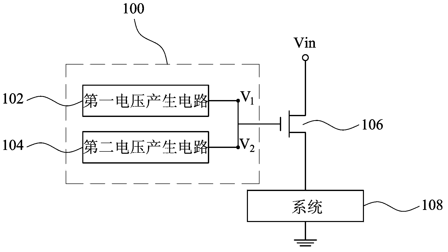
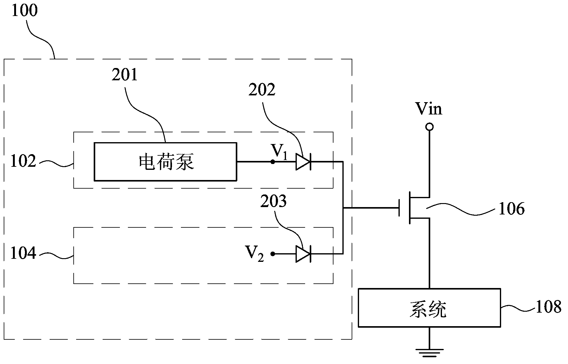
[0011] figure 1 It is a schematic diagram of a transistor switch gate voltage generating circuit according to an embodiment of the present invention. The gate voltage generation circuit 100 is used to provide a first voltage and a second voltage to the gate of a transistor switch 106 to turn on the transistor switch 106 to provide an operating voltage Vin to the system 108 . The gate voltage generating circuit 100 includes a first voltage generating circuit 102 and a second voltage generating circuit 104 . Wherein, the first voltage generating circuit 102 is realized by a charge pump circuit to provide a first voltage V1 to the gate of the transistor switch 106 . The se...


PUM


Abstract

A grid voltage generating circuit is used to provide a grid voltage to a transistor switch, and comprises a first voltage generating circuit and a second voltage generating circuit. The first voltage generating circuit is used to provide a first voltage to a grid of the transistor switch, and the second voltage generating circuit is used to provide a second voltage to the grid of the transistor switch, wherein the second voltage is at least greater than a voltage needed to conduct the transistor switch, and the first voltage is greater than the second voltage.

Description

technical field [0001] The invention relates to a voltage generation circuit, in particular to a gate voltage generation circuit of a transistor switch. Background technique [0002] Traditionally, in order to switch the transistor switch, a gate voltage supply circuit is usually coupled to the gate of the transistor switch to supply a high level voltage to turn on the transistor switch. The gate voltage supply circuit is generally realized by a charge pump circuit, so as to provide a voltage higher than the voltage required to turn on the transistor switch, so as to continuously reduce the transistor switch after the transistor switch is turned on. resistor between drain and source, reducing power loss. [0003] However, using a charge pump circuit requires a specific charging time to reach the voltage required to turn on the transistor switch. For electrical devices that require fast startup, this charging time becomes the bottleneck of whether the electrical device can b...

Claims


Application Information

Patent Timeline
Patent Type & Authority Applications(China)
IPC IPC(8): H03K17/04
Inventor 张正文
Owner ADVANCED POWER ELECTRONICS CORP
Why Eureka
Try Eureka