Timestamp generation method, device and system

A time stamp and precise time technology, applied in the field of communication, can solve the problems of low time stamp precision and low time synchronization precision of communication network.

Inactive Publication Date: 2014-10-22
HUAWEI TECH CO LTD
View PDF3 Cites 18 Cited by
  • Summary
  • Abstract
  • Description
  • Claims
  • Application Information

AI Technical Summary

Problems solved by technology

However, the time stamp accuracy obtained by this method is not high, which in tu

Method used


Image

  • Timestamp generation method, device and system
  • Timestamp generation method, device and system
  • Timestamp generation method, device and system

Examples


Embodiment Construction

[0037]In order to make the purpose, technical solutions and advantages of the embodiments of the present invention clearer, the technical solutions in the embodiments of the present invention will be clearly and completely described below in conjunction with the drawings in the embodiments of the present invention. Obviously, the described embodiments It is a part of embodiments of the present invention, but not all embodiments. Based on the embodiments of the present invention, all other embodiments obtained by persons of ordinary skill in the art without making creative efforts belong to the protection scope of the present invention.

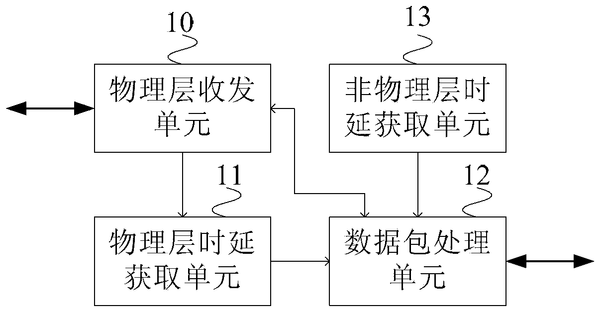
[0038] figure 1 A schematic diagram of the network node structure provided by Embodiment 1 of the present invention, such as figure 1 As shown, the network node includes: a physical layer transceiver unit 10, a data packet processing unit 12, a physical layer delay acquisition unit 11, and a non-physical layer delay acquisition unit 13;

[0...


PUM


Abstract

The invention provides a timestamp generation method, a device and a system. The timestamp generation method comprises the following steps: a data packet processing unit receives a data packet transmitted by a physical layer receiving/transmitting unit or a higher layer; whether the data packet is a precise time synchronization protocol PTP packet is identified; and if the data packet is a precise time synchronization protocol PTP packet, a precise timestamp is generated according to physical layer delay provided by a physical layer delay acquisition unit and non-physical layer delay provided by a non-physical layer delay acquisition unit, and the timestamp field of the data packet is rewritten. The precision of timestamp is effectively improved, and the precision of time synchronization of the whole communication network is improved.

Description

technical field [0001] The present invention relates to communication technology, in particular to a time stamp generation method, device and system. Background technique [0002] With the development of communication technology, communication networks have higher and higher requirements for time synchronization. Existing communication networks require time synchronization at the sub-microsecond level. In the future, it is possible to use large-scale cooperative communication. Therefore, multi-cell, multi-antenna cooperative communication may require nanosecond or even sub-nanosecond level time synchronization. IEEE1588V2 Time Synchronization Protocol (Precision Time Protocol, referred to as: PTP) realizes the time synchronization of the entire network by sending PTP data packets containing time stamps between communication network nodes. It is a more accurate time synchronization scheme at present. [0003] In the prior art, after a communication network node receives a P...

Claims


Application Information

Patent Timeline
IPC IPC(8): H04L29/06H04J3/06
CPCH04J3/0697H04J3/0667
Inventor 赵国栋李波杰张锦芳
Owner HUAWEI TECH CO LTD
Why Eureka
Try Eureka