Ultrasonic imaging device

A technology of imaging device and ultrasonic wave, applied in the direction of measurement device, acoustic wave diagnosis, infrasound wave diagnosis, etc., can solve problems such as the change of ultrasonic image quality, and achieve the effect of reducing signal loss and high robustness.

Inactive Publication Date: 2014-10-22
HITACHI LTD
View PDF11 Cites 9 Cited by
  • Summary
  • Abstract
  • Description
  • Claims
  • Application Information

AI Technical Summary

Problems solved by technology

In the existing delay and addition method, the correction of wavefront deformation has long been a subject, and the aberration correction technology using cross-correlation processing has been studied. In the adaptive beamformer, the inhomogeneity in the medium causes the image quality of the ultrasonic image to be poor. Big changes are also a topic

Method used


Image

  • Ultrasonic imaging device
  • Ultrasonic imaging device
  • Ultrasonic imaging device

Examples


no. 1 Embodiment approach

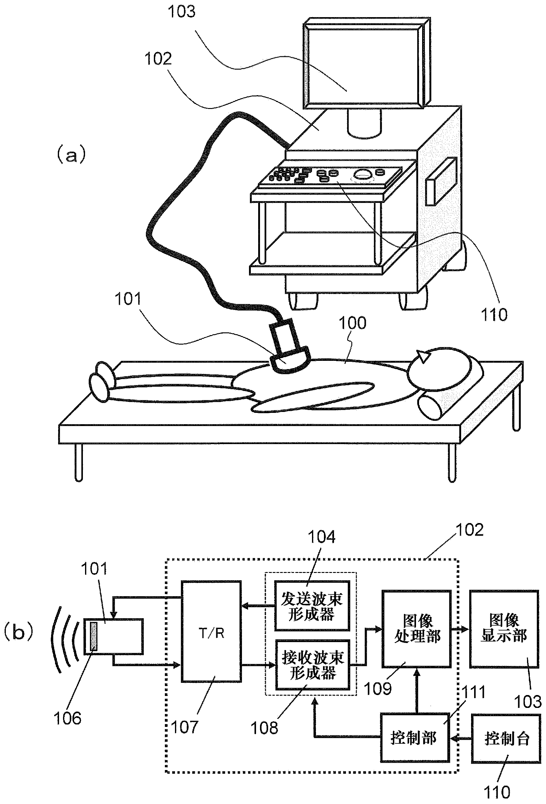
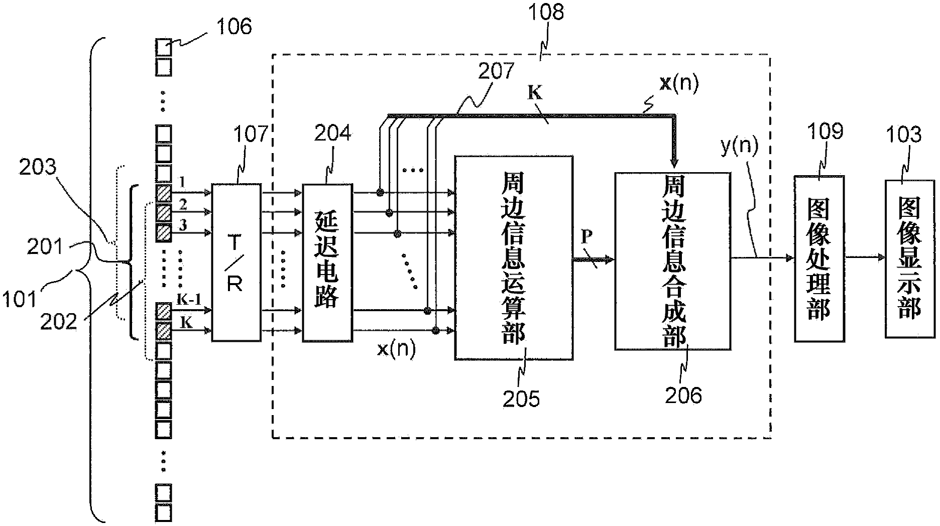
[0060] The ultrasonic imaging device according to the first embodiment includes: a plurality of elements that receive ultrasonic signals from the subject; and a delay unit that delays the reception signals received by the plurality of elements in accordance with the position of a predetermined reception focus, generates delays and receives the signals received by the plurality of elements. a signal; a surrounding information computing unit; a surrounding information synthesizing unit; and an image processing unit. The peripheral information calculation unit acquires information on a reception focus and a plurality of points in a surrounding area of ​​the reception focus from the delayed reception signal. The peripheral information synthesis unit synthesizes the information obtained for the plurality of points, and generates a phase adjustment output using the synthesized information. The image processing unit generates image data using the phase adjustment output. Hereinafter...

no. 2 Embodiment approach

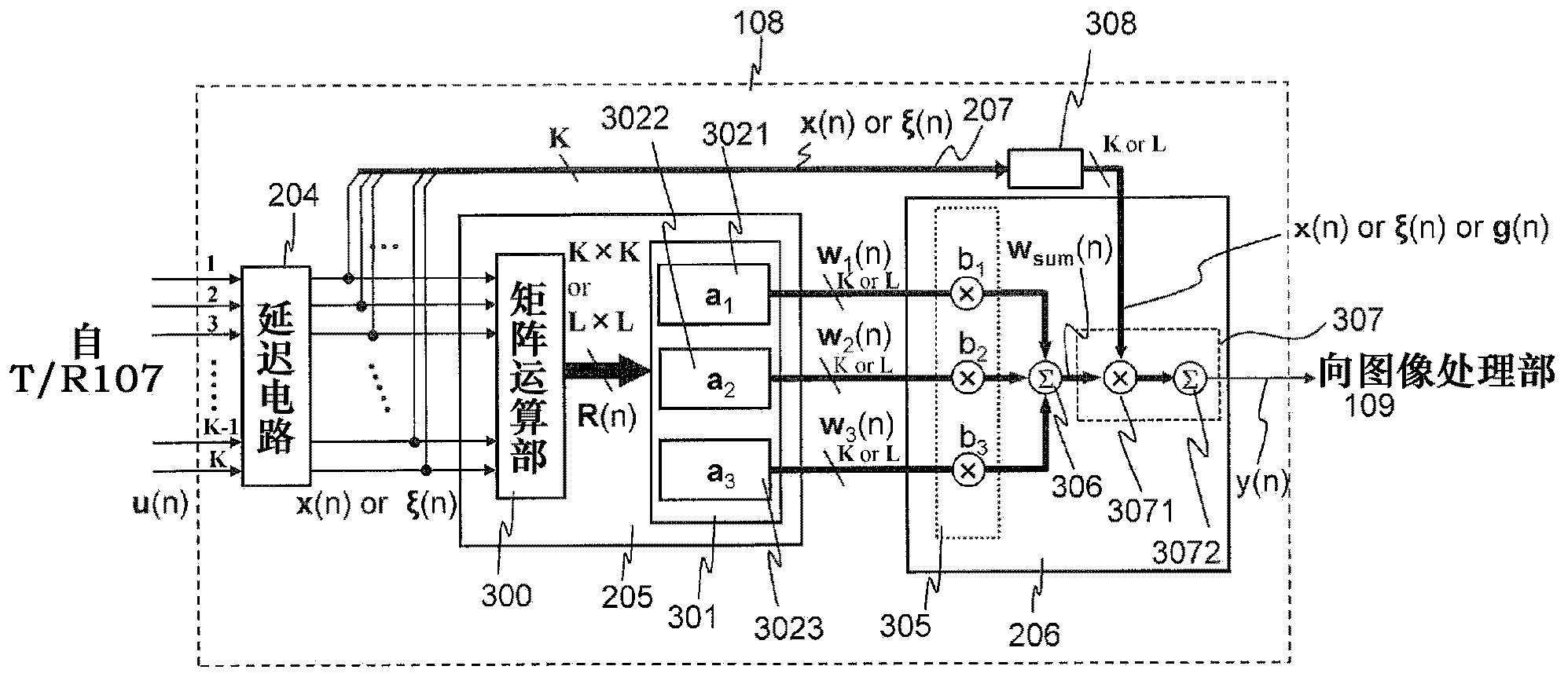
[0072] In the second embodiment, in the ultrasonic imaging device of the first embodiment, the peripheral information computing unit 205 performs adaptive beamforming to obtain adaptive weights as information.

[0073] The peripheral information calculation unit 205 is configured to obtain the direction vectors for the plurality of points using the steering vectors that connect predetermined positions on the array surface composed of the plurality of elements 106 described in the first embodiment and the plurality of points. Adaptive weights.

[0074] Further, the surrounding information calculation unit 205 is configured to include: a matrix calculation unit that generates a covariance matrix using the delayed received signal; and obtains adaptive weight vectors for the above-mentioned multiple points according to the covariance matrix and the above-mentioned steering vector The weight vector operation part of . The surrounding information combining unit 206 is configured to...

no. 3 Embodiment approach

[0157] In the third embodiment, unlike the second embodiment, the surrounding information synthesizing unit 206 multiplies the delayed received signal by the adaptive weights for a plurality of points obtained by the surrounding information calculating unit 205 to generate multiple points. a plurality of inner product operation sections of the pre-synthesis phase-adjusted output of each of the adaptive weights; and an output synthesis section. The output combination unit adds and combines pre-synthesis phase adjustment outputs for each of the plurality of adaptive weights to generate a phase adjustment output used for generating image data.

[0158] Between the surrounding information calculating unit 205 and the plurality of inner product calculating units, a fixed apodization multiplying unit may be arranged, and the fixed apodization multiplying unit, for the adaptive weights for the plurality of points obtained by the surrounding information calculating unit 205, Multiplie...


PUM


Abstract

The invention makes it possible to more precisely compensate, with less computation, for image quality degradation caused by wavefront distortion in an ultrasonic imaging device, while being a technique for adaptive signal processing. An ultrasonic signal coming from a subject is received by elements (106), and received signals received by a plurality of the elements are delayed by a delay circuit (204) in accordance with the position of a predetermined reception focal point. A periphery information computation unit (205) acquires from each of the delayed received signals information regarding the reception focal point and a plurality of points in a periphery region of the reception focal point. As an example, adaptive weightings corresponding to a plurality of steering angles are established. A periphery information compositing unit (206) composites a plurality of sets of information (the adaptive weightings), and the composited information is used to generate a phasing output. Alternatively, the plurality of adaptive weightings and the received signals are used to generate phasing outputs, which are then composited.

Description

technical field [0001] The present invention relates to an ultrasonic imaging technique for imaging images inside a subject using ultrasonic waves. Background technique [0002] The so-called ultrasonic imaging technology refers to the technology of non-invasively imaging the inside of the subject including the human body by using ultrasonic waves (sound waves that are unintentionally heard, generally high-frequency sound waves of 20 kHz or higher). As an example, a medical ultrasonic imaging device will be briefly described. The ultrasonic probe transmits ultrasonic waves into the patient's body and receives echo signals reflected from the patient's body. The received signal is subjected to signal processing by one or both of the ultrasonic probe and the main body of the ultrasonic imaging device, and then transferred to the image display unit to display an ultrasonic image. To describe in more detail, for example, a transmission beamformer in the main body of an ultrason...

Claims


Application Information

Patent Timeline
Patent Type & Authority Applications(China)
IPC IPC(8): A61B8/00
CPCG10K11/346A61B8/5207G01S15/8993G01S7/52049A61B8/5269A61B8/14A61B8/4483A61B8/465G01S15/8915
Inventor 池田贞一郎鳟泽裕田原麻梨江高野慎太桥场邦夫
Owner HITACHI LTD
Why Eureka
Try Eureka