Electric auxiliary device for increasing walking speed
An electric assist and walking speed technology, applied in applications, clothing, footwear, etc., can solve problems such as low safety, poor stability, and difficult use, and achieve the effect of small device size, high safety, and easy portability
- Summary
- Abstract
- Description
- Claims
- Application Information
AI Technical Summary
Problems solved by technology
Method used
Image

Examples
specific Embodiment approach 1
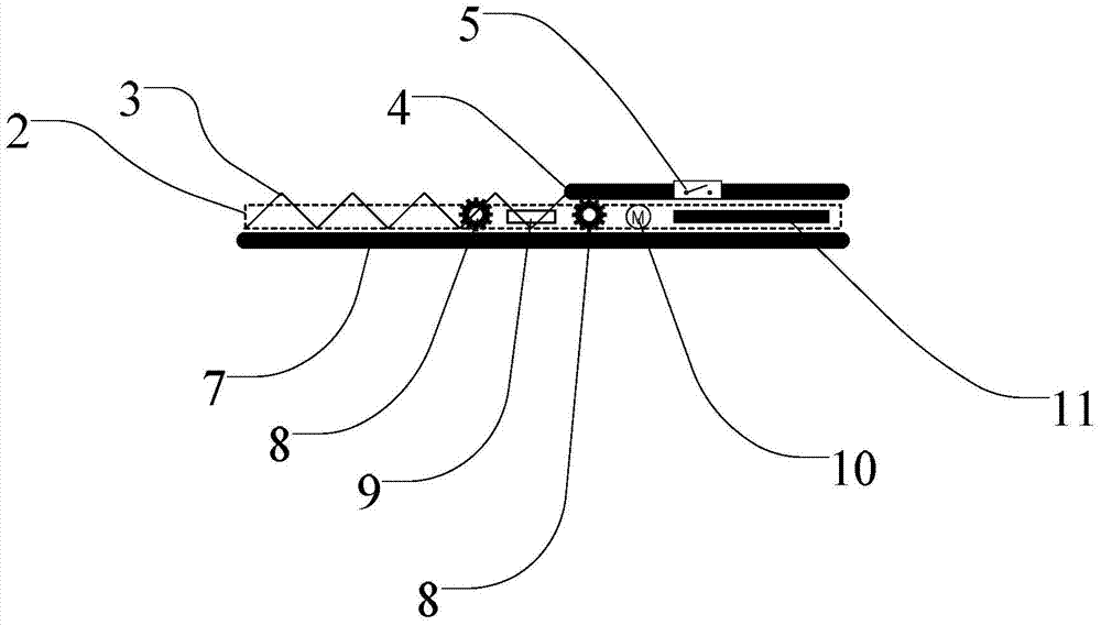
[0007] Specific implementation mode 1. Combination figure 1 Describe this specific embodiment. The electric auxiliary device for accelerating walking speed described in this specific embodiment includes a foot-operated electric device, and the foot-operated electric device includes a base plate 7, a gear 8, a motor 10, a motor control circuit 9, two A ball slide 2, a sole fixing plate 4, a pressure switch 5 and a battery 11, the two ball slides 2 are fixed on the base plate 7 in parallel, the sole fixing plate 4 is mounted on the ball slide 2, and the motor 10 and the motor control circuit 9 are all installed on the base plate 7, the pressure switch 5 is installed in the sole fixed plate 4, and is used to sense the sole pressure, the switch signal output end of the pressure switch 5 is connected with the switch signal input end of the motor control circuit 9, and the motor The motor 10 control signal output end of the control circuit 9 is connected with the control signal inpu...
specific Embodiment approach 2
[0008] Specific embodiment two, combine figure 1 This specific embodiment is described. The difference between this specific embodiment and the electric auxiliary device for accelerating walking speed described in the first specific embodiment is that it also includes a spring 3, which is installed on the front end of the bottom plate 7 for Energy is stored in the process of the sole fixing plate 4 sliding forward.
[0009] When a person is walking and one foot leaves the ground and moves forward, the pressure switch 5 is disconnected, the motor control circuit 9 controls the motor 10 to reverse, and the sole fixing plate 4 is moved backward relative to the bottom plate 7, while stretching The energy storage spring 3 stores the energy of the motor's work; when the foot is on the ground, the pressure switch 5 is closed, the motor control circuit 9 controls the motor 10 to rotate forward, and the sole fixing plate 4 is moved forward relative to the bottom plate 7, and energy is ...
specific Embodiment approach 3
[0010] Embodiment 3. The difference between this embodiment and the electric auxiliary device for speeding up walking described in Embodiment 1 is that the distance that the sole fixing plate 4 slides back and forth relative to the bottom plate 7 is 20cm-30cm.
PUM
 Abstract
Description
Claims
Application Information
 - Generate Ideas
- Intellectual Property
- Life Sciences
- Materials
- Tech Scout
- Unparalleled Data Quality
- Higher Quality Content
- 60% Fewer Hallucinations
Browse by: Latest US Patents, China's latest patents, Technical Efficacy Thesaurus, Application Domain, Technology Topic, Popular Technical Reports.
© 2025 PatSnap. All rights reserved.Legal|Privacy policy|Modern Slavery Act Transparency Statement|Sitemap|About US| Contact US: help@patsnap.com