Metal plate punching device

A punching device and punching technology, applied in the field of sheet metal processing, can solve the problems of low hole processing quality, affecting the quality of the sheet, and many burrs on the edge of the hole, so as to reduce the burr on the edge of the hole, improve the quality and structure of the punching hole. Sophisticated effect

Inactive Publication Date: 2014-10-29
SUZHOU CHENXITE SHEET METAL PROD
View PDF7 Cites 8 Cited by
  • Summary
  • Abstract
  • Description
  • Claims
  • Application Information

AI Technical Summary

Problems solved by technology

The disadvantages of the above-mentioned punching device or punching machine are: the punching head has more burrs on the edge of the hole after punching, and the hole processing quality is not high; quality

Method used


Image

  • Metal plate punching device

Examples


Embodiment Construction

[0010] The specific embodiments of the present invention will be described below in conjunction with the drawings.

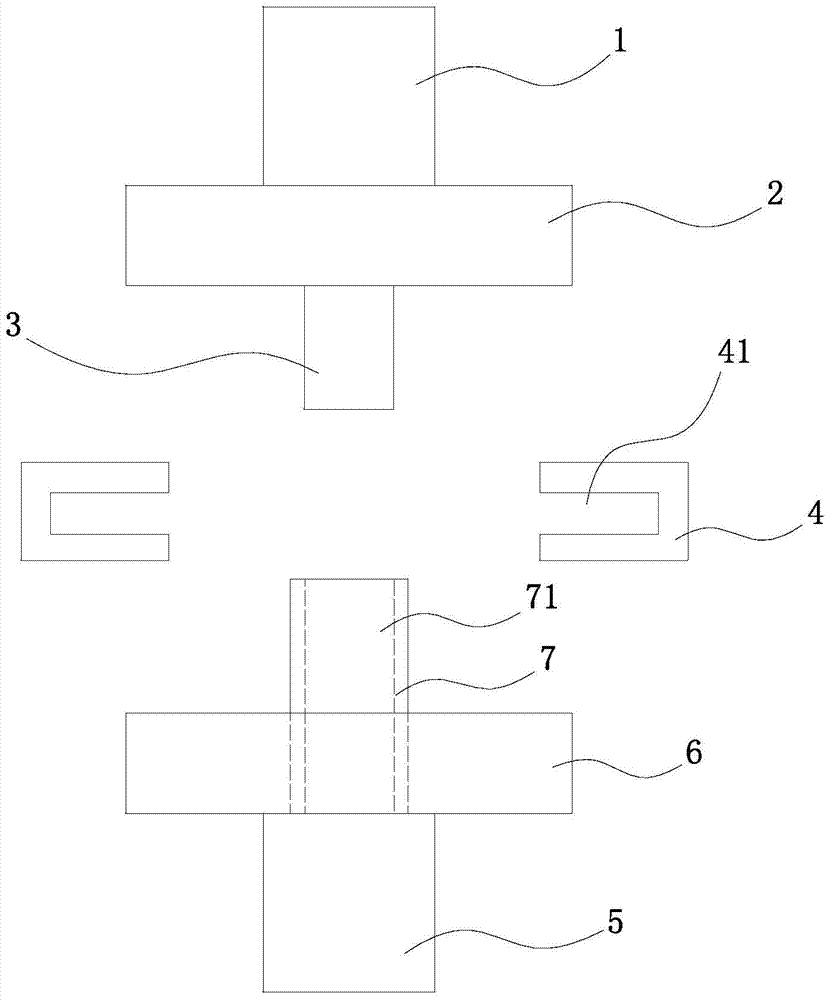
[0011] see figure 1 , The present invention includes a punching drive device 1, an upper template 2 and a punching head 3. It also includes a clamping block 4 and a fixing block 7 located below the punching head 3. The clamping blocks 4 are symmetrically arranged on the two sides of the punching head 3. On the other hand, the clamping block 4 uses the clamping groove 41 on its inner side to fix the workpiece; the fixing block 7 is a cylindrical structure with a through hole 71, the inner diameter of the through hole 71 is greater than or equal to the outer diameter of the punching head 3, so that The punching head 3 can just be placed in the through hole 71; the fixing block 7 is fixed in the mounting hole of the base 6, and the bottom surface of the base 6 is installed with a waste barrel 5 connected to the through hole 71 of the fixing block 7 for the waste barre...


PUM


Abstract

The invention relates to a metal plate punching device which comprises a punching drive device, an upper die plate and a punching head. The metal plate punching device further comprises clamping blocks located below the punching head, and a fixing block. The clamping blocks are symmetrically arranged on the two sides of the punching head. The fixing block is of a cylindrical structure with a through hole. The inner diameter of the through hole is larger than or equal to the outer diameter of the punching head. The fixing block is fixedly connected into an installation hole of the base. The lower surface of the base is provided with a waste barrel communicated with the through hole of the fixing block. The metal plate punching device is ingenious in structure; the punching head of the upper portion and the fixing block of the bottom are combined for punching, deformation of a machined part is reduced, the punching quality is improved, and burrs on the edges of holes are reduced.

Description

Technical field [0001] The invention relates to the technical field of sheet metal processing, in particular to a punching machine for sheet metal. Background technique [0002] Existing punching devices or punching machines all include a frame, a bottom mold fixed on the frame, and an upper template that moves up and down relative to the frame, and a punch corresponding to the bottom mold is fixed on the upper template , The upper template is connected with the oil cylinder or air cylinder that drives it to move up and down. Driven by the oil cylinder or the air cylinder, the upper template drives the punch to move up and down relative to the bottom mold, thereby punching the required holes on the workpiece between the punch and the bottom mold. The disadvantages of the above-mentioned punching device or punching machine are: the punching head has more burrs on the edge of the hole after punching, and the quality of the hole processing is not high; after punching, the processed...

Claims


Application Information

Patent Timeline
Patent Type & Authority Applications(China)
IPC IPC(8): B21D28/26B21D43/00
Inventor 蒋冰清
Owner SUZHOU CHENXITE SHEET METAL PROD
Why Eureka
Try Eureka