Roll forming die for disposable sanitary products

A technology for sanitary products and roll forming, applied in metal processing and other directions, can solve the problems of increasing processing cost, mold loss, incomplete cutting, etc., and achieve the effects of improving coaxiality accuracy, reducing mold cost, and improving installation efficiency.

Active Publication Date: 2014-10-29
泉州市振鑫机械制造有限公司
View PDF9 Cites 2 Cited by
  • Summary
  • Abstract
  • Description
  • Claims
  • Application Information

AI Technical Summary

Problems solved by technology

[0004] 1. The processing of the middle shaft in the upper roller has high requirements for coaxiality, and the installation of the upper roller parts is complicated. At the same time, the installation structure mostly adopts interference fit, which needs to be installed by knocking, and the coaxiality cannot be achieved after the installation is completed. At the same time, the loss of the mold is serious, and the upper roller cannot press the lower roller, and it cannot be completely cut under the condition of high-speed operation. At the same time, the processing of high coaxiality increases the processing cost;
[0005] 2. Although the center shaft adjustment sleeve and the movable knife mold structure in the upper roller can avoid the hard friction and wear of the upper roller to the lower roller, they will jump when moving at high speed, making the cutting incomplete;
[0006] 3. The current upper roller and lower roller are fixed on the formwork through the central shaft, the installation structure is complicated and the cost is high

Method used


Image

  • Roll forming die for disposable sanitary products
  • Roll forming die for disposable sanitary products
  • Roll forming die for disposable sanitary products

Examples


Embodiment Construction

[0024] The present invention will be further described below in conjunction with the accompanying drawings and specific embodiments.

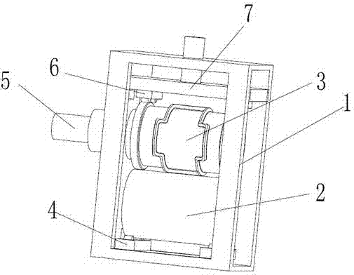
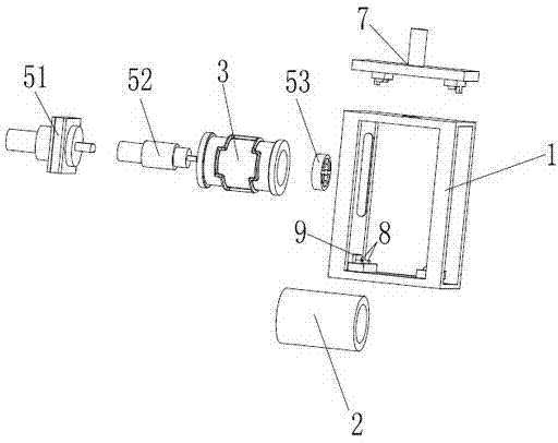
[0025] figure 1 , figure 2 , image 3 The roll forming die of the shown disposable sanitary product comprises a mold base 1, a lower roll 2 and an upper roll 3, and the lower roll 2 and the upper roll 3 are assembled and fixed on the mold base 1 in parallel, and the lower roll 2 and the upper roll 3 are fixed on the mold base 1 in parallel. The upper rollers 3 are cylinders, most preferably hollow cylinders, the lower rollers 2 are placed on the bottom of the formwork 1, and the axial position is positioned by the first positioning part 4 fixed on the bottom of the formwork 1. One side of the upper roller 3 locates the radial position of the upper roller through the driving part 5 and the formwork 1, the second positioning part 6 locates the axial position of the upper roller 3, and the second positioning part 6 is fixedly connected with the...


PUM


Abstract

Disclosed is a roll forming die for disposable sanitary products. The roll forming die comprises a die carrier, a lower roll and an upper roll. The lower roll and the upper roll are fixedly assembled to the die carrier in parallel. The lower roll and the upper roll are cylinders. The lower roll is placed to the bottom of the die carrier, and the axial position of the lower roll is positioned through a first positioning portion fixed to the bottom of the die carrier. The radial position of one side of the upper roll is positioned through a driving portion and the die carrier, the axial position of the upper roll is positioned through a second positioning portion, the second positioning portion is fixedly connected with a compression portion, the compression portion is movably connected to the die carrier, the compression portion applies pressure downwards, pressure is transmitted downwards through the second positioning portion to the upper roll and the lower roll and enables the upper roll and the lower roll to make contact with each other and to be fixed together, power drives the upper roll to rotate through the driving portion, the upper roll rotates to drive the lower roll to rotate, and the first positioning portion and the second positioning portion simultaneously rotate to reduce friction force generated when the lower roll and the upper roll rotate. According to the technical scheme, the roll forming die is low in cost and loss and easy to install, and stably runs during high-speed machining.

Description

technical field [0001] The invention belongs to the field of disposable hygienic products, in particular to a roll forming mold for disposable hygienic products. Background technique [0002] Disposable hygienic products include diapers, sanitary napkins, sanitary pads, paper bibs, breast pads, paper insoles, etc. Currently, the existing production of disposable hygienic products adopts the structure of rolling forming molds: the upper roller is a forming knife, divided into For forming the knife edge part, the protective cover part, the central axis part, the knife edge part is 0.01 ~ 0.05mm higher than the protective cover part, and the knife edge is sharpened; the lower roller is divided into a smooth and flat roller body part and a central axis part. The upper and lower rollers are assembled on the same frame, the lower roller is fixed, the upper roller can move up and down, pressurized by the spring (or air pressure, oil pressure) device, the upper and lower rollers...

Claims


Application Information

Patent Timeline
IPC IPC(8): B26F1/44B26D7/01
Inventor 王振明
Owner 泉州市振鑫机械制造有限公司
Why Eureka
Try Eureka