Spiral conveying and drying device

A technology of screw conveying and drying device, applied in heating device, progressive dryer, drying and other directions, can solve the problems of flow to drying section, waste of cleaning liquid, low conveying efficiency, etc.

Active Publication Date: 2014-10-29
SHENZHEN KAIZHONG PRECISION TECH CO LTD
View PDF11 Cites 3 Cited by
  • Summary
  • Abstract
  • Description
  • Claims
  • Application Information

AI Technical Summary

Problems solved by technology

[0006] In this prior art, the drying section is arranged behind the cleaning pipe and inside the screw conveying drum together. This arrangement, on the one hand, will cause the cleaning liquid in the cleaning section to enter the drying section along with the materials, which will affect the The drying effect of the drying section will affect the subsequent drying process and lead to the waste of cleaning liquid. On the other hand, when drying at high temperature, the liquid cannot be discharged in time when it is vaporized, so it is easy to be transported with the screw. The inner wall of the drum contacts and is cooled and liquefied, which leads to poor drying effect; therefore, this method of setting the drying section inside the spiral drum is not advisable
However, if the drying section is simply set outside the screw conveyor drum, the cleaned materials will enter the drying section from the feeding mechanism, and there is also the problem that the cleaning liquid will enter the drying section together with the materials, which will affect the drying effect. Therefore, in order to prevent the cleaning liquid in the screw conveyor drum from entering the drying section, the traditional solution is to set a valve between the screw conveyor drum and the drying section. The valve is closed when cleaning and degreasing, and the valve is opened when cleaning and degreasing is completed. However, when the valve is opened, the cleaning liquid will still enter the drying section with the material, which cannot completely solve the problem of poor drying effect. Therefore, simple control through the valve cannot overcome the cleaning in the screw conveyor drum when the material passes through. The liquid will flow to the drying section, affecting the drying effect of the drying section, and switching the valve back and forth leads to low transmission efficiency

Method used


Image

  • Spiral conveying and drying device
  • Spiral conveying and drying device
  • Spiral conveying and drying device

Examples


Embodiment Construction

[0046] The specific embodiments of the present invention will be described in detail below with reference to the accompanying drawings. It should be understood that the specific embodiments described herein are only used to illustrate and explain the present invention, and not to limit the present invention.

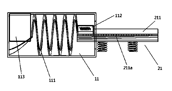
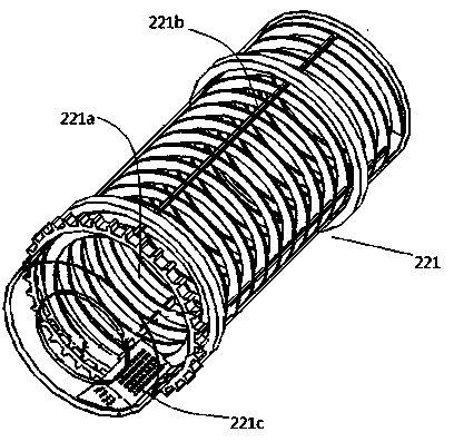
[0047] This embodiment provides a screw conveying drying device, which includes a feeding component 1 and a drying component 2. The feeding component 1 is used to receive cleaned materials from the cleaning section and transport the materials to the drying section; the drying component 2 is used to receive the materials sent from the feeding assembly 1, dry the materials and output the materials.

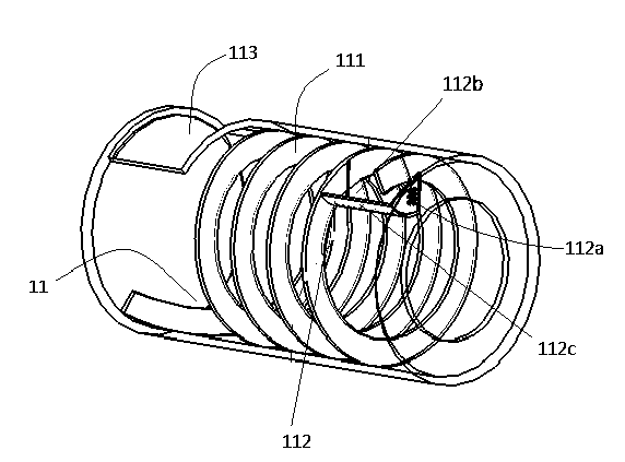
[0048] Such as figure 1 As shown, the feed assembly 1 of this embodiment includes a revolving drum 11, one end of the revolving drum 11 is suitable for being connected to the material outlet of the cleaning section and receiving cleaned materials, and the revolving drum 11 is conne...


PUM


Abstract

The invention provides a spiral conveying and drying device. The spiral conveying and drying device comprises a feeding assembly and a drying assembly, wherein the feeding assembly is used for receiving materials cleaned in a cleaning section and conveying the materials to a drying section; the drying assembly is used for receiving the materials sent by the feeding assembly and drying the materials; the feeding assembly comprises a circulation roller, and one end of the circulation roller is suitable for being connected to a material outlet of the cleaning section and receiving the cleaned materials; the inner wall of the circulation roller is provided with a spiral conveying channel and a bucket, a drainage port and a bucket opening are formed in the bucket, and the bucket opening corresponds to a discharge port of the spiral conveying channel; in the rotating process of the circulation roller, the bucket opening receives the materials from the discharge port and dumps the materials into the drying assembly. The spiral conveying and drying device achieves the conveying function and has a good drying effect.

Description

Technical field [0001] The invention relates to a drying device, in particular to a device for spirally conveying materials and drying the materials. Background technique [0002] With the development of society and the progress of the times, people have higher and higher requirements for the quality of ring mirrors. Therefore, environmental protection has become a common concern in today's society. The recycling of industrial waste can not only reduce environmental pollution, but also save energy, which plays a positive role in driving social benefits. [0003] The recycling and reuse of industrial waste first requires decontamination and cleaning of industrial waste. Taking the recycling and reuse of scrap copper as an example, the oil attached to the scrap copper should be removed first. The traditional method of degreasing copper scrap is manual removal. Oil pollution, in this way, not only wastes time and increases labor intensity, but also has a poor decontamination effect, ...

Claims


Application Information

Patent Timeline
Patent Type & Authority Applications(China)
IPC IPC(8): F26B15/26F26B23/10
Inventor 张浩宇
Owner SHENZHEN KAIZHONG PRECISION TECH CO LTD
Why Eureka
Try Eureka