Gate water-stop dam face unevenness underwater measuring device and method

A technology of underwater measurement and water stop dam, applied in the direction of measuring devices, instruments, etc., can solve the problems of affecting the water sealing effect of the floating gate, unevenness of the dam surface, and difficulty in construction

Inactive Publication Date: 2014-10-29
POWERCHINA XIBEI ENG
View PDF2 Cites 6 Cited by
  • Summary
  • Abstract
  • Description
  • Claims
  • Application Information

AI Technical Summary

Problems solved by technology

[0002] After years of operation of the hydropower station and the erosion of sand-entrained water, some discharge structures have been damaged. If they are not repaired in time, the operation safety of the power station will be directly affected
However, these scuppers or drains are located tens or even hundreds of meters underwater, and the construction is difficult. Currently, the technology adopted is to design a floating maintenance gate on the upstream dam surface outside the bell mouth of the drain hole or the inlet of the drain. , to create dry land construction conditions for the repair of damaged parts
[0003] The technical key to the blockage of the floating gate of the release channel is the water-stopping effect of the gate, and the water-stop surface of the floating gate of most large and medium-sized hydropower station's scupper and discharge channel restoration projects is due to the construction quality problems at that time, or due to the long-term erosion and erosion of the water flow. , there are local pits, bosses and penetrating grooves, bumps and other defects that cause the unevenness of the dam surface. Such dam surface defects will affect the water sealing effect of the floating gate, thereby affecting the quality of the repair project

Method used


Image

  • Gate water-stop dam face unevenness underwater measuring device and method
  • Gate water-stop dam face unevenness underwater measuring device and method
  • Gate water-stop dam face unevenness underwater measuring device and method

Examples


Embodiment 1

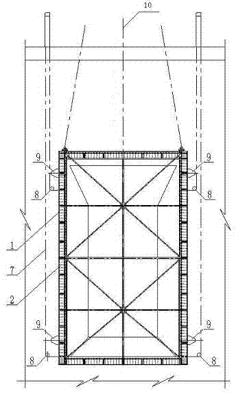
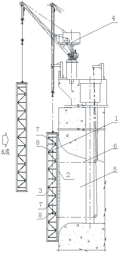
[0028] The underwater measuring device for the unevenness of the gate water stop dam surface of the present invention is specifically a measurement frame 1, the downstream surface of the measurement frame 1 and the corresponding position of the gate water stop dam surface are provided with uniformly arranged measuring needles 2, and the measurement The needle 2 is movably connected with the measuring frame 1, and can expand and contract along the direction vertical to the dam surface.

[0029] The measuring needle 2 can form a curved surface through expansion and contraction, and the formed curved surface is the surface of the water stop dam to be blocked. The structure of measurement box 1 is as follows figure 1 and figure 2 shown.

Embodiment 2

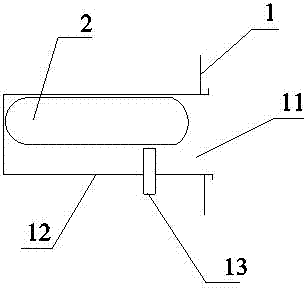
[0031] In this embodiment, on the basis of Embodiment 1, as a preference, a probe hole 11 is provided on the downstream surface of the measurement frame 1 corresponding to the surface of the gate dam, and a probe hole 11 is provided in the probe hole 11. cylinder 12, the needle cylinder 12 is provided with a needle 2, the needle 2 can be extended and retracted along the direction vertical to the dam surface, and a bolt 13 is also arranged in the needle cylinder, and the bolt 13 is perpendicular to the needle 1 , to fix or loosen stylus 1. image 3 It is an enlarged cross-sectional view of the stylus cylinder 12 when the stylus 2 is received in the stylus cylinder 12, and the bolt 13 is in a loosened state in the figure; Figure 4 It is an enlarged cross-sectional view of the stylus cylinder 12 when the stylus 2 extends out of the stylus cylinder 12. In the figure, the bolt 13 is in a tightened state, and the stylus 2 is fixed at this time.

[0032] Before the measuring frame ...

Embodiment 3

[0034] In this embodiment, on the basis of embodiments 1 and 2, the downstream surface of the measuring frame 1 and the corresponding part of the gate dam surface are provided with evenly arranged measuring needles 2, and the arrangement spacing of the measuring needles 2 on the measuring frame is 100 ~ 300mm. The size of the spacing depends on the measurement accuracy of the measured curved surface, and the number of measuring needles 2 is hundreds or thousands, forming a needle comb. The stylus 2 is rod-shaped, which can be a nylon rod or a wooden rod, or other rod-shaped materials with certain strength and lightness for underwater operation. The top of the stylus 2 is smooth.

[0035] In this embodiment, the water stop surface of the gate to be measured by the measurement frame 1 is the uneven concrete dam surface, and the measurement range is the height of local pits, bosses and penetrating grooves within the water stop zone of the concrete dam surface. value, the stretchi...


PUM


Abstract

The invention discloses a gate water-stop dam face unevenness underwater measuring device and method. In specific, the measuring device is a measuring frame, uniformly ranked measuring needles are arranged on a portion, corresponding to a gate water-stop dam face, of a downstream face of the measuring frame, and the measuring needles are movably connected with the measuring frame and can telescope along the direction perpendicular to the dam face. The measuring method includes steps of achievement of deepwater guide in-placement of the measuring frame, measurement, data analysis and the like. After the measuring frame is put in place, the measuring needles are pushed along the direction perpendicular to the dam face and pulled out of the water surface after tightening and fixing, a curved surface formed by the measuring needles is the water-stop dam face to be blocked, measurement data of the measuring needles are analyzed and processed to obtain dam face unevenness within a water-stop zone, and the unevenness can be used as a basis for designing a floating gate water seal, so that the basis problem of designing the floating gate water seal is solved. According to the gate water-stop dam face unevenness underwater measuring device and method, a plurality of novel techniques such as a gilling truss structure, deepwater guide in-placement, and one-step modeling of thousands of unevenness height values within the range of the water-stop zone are created in design.

Description

technical field [0001] The invention belongs to the technical field of hydropower station maintenance, and relates to a measurement method, in particular to an underwater measurement device and measurement method for the unevenness of a sluice stop dam surface. Background technique [0002] After many years of operation of the hydropower station and the erosion of sand-entrained water, some discharge structures have been damaged. If they are not repaired in time, the operation safety of the power station will be directly affected. However, these scuppers or drains are located tens or even hundreds of meters underwater, and the construction is difficult. Currently, the technology adopted is to design a floating maintenance gate on the upstream dam surface outside the bell mouth of the drain hole or the inlet of the drain. , Create dry land construction conditions for the repair of damaged parts. [0003] The technical key to the blockage of the floating gate of the release c...

Claims


Application Information

Patent Timeline
Patent Type & Authority Applications(China)
IPC IPC(8): G01B21/30
Inventor 丁晓利廖永平方勇朱增兵郭富权李岗罗涛
Owner POWERCHINA XIBEI ENG
Why Eureka
Try Eureka