Electric connector

A technology of electrical connectors and arcs, applied in the direction of the base/housing, etc., can solve problems such as electrical connector arcing, and achieve the effect of reducing the possibility of operator safety

Active Publication Date: 2014-10-29
HUAWEI TECH CO LTD
View PDF4 Cites 4 Cited by
  • Summary
  • Abstract
  • Description
  • Claims
  • Application Information

AI Technical Summary

Problems solved by technology

[0004] The embodiment of the present invention provides an electrical connector to solve the arcing problem of the existing electrical connector during the hot plugging process, so as to improve the life of the electrical connector and enhance the safety protection of the operator

Method used


Image

  • Electric connector
  • Electric connector
  • Electric connector

Examples


Embodiment Construction

[0021] The following will clearly and completely describe the technical solutions in the embodiments of the present invention with reference to the accompanying drawings in the embodiments of the present invention. Obviously, the described embodiments are only some of the embodiments of the present invention, not all of them. Based on the embodiments of the present invention, all other embodiments obtained by persons of ordinary skill in the art without creative efforts fall within the protection scope of the present invention.

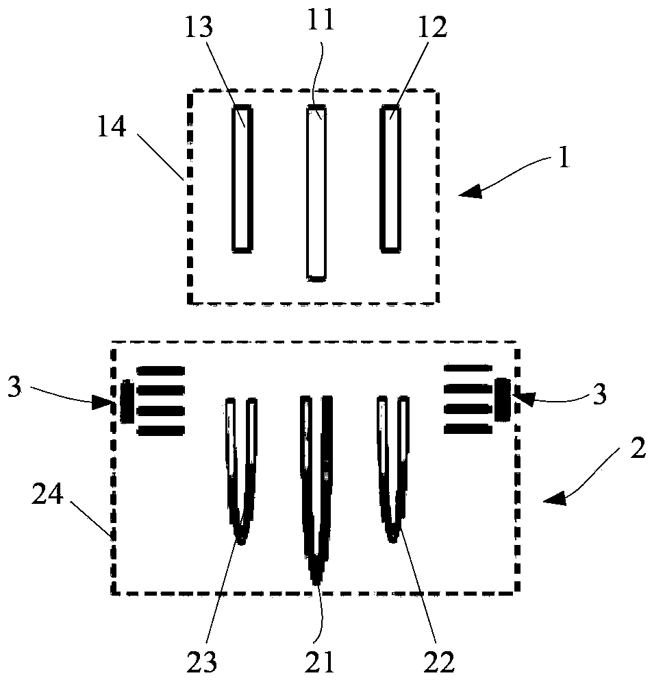
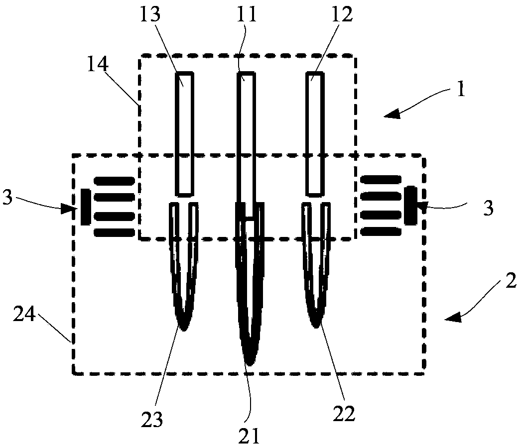
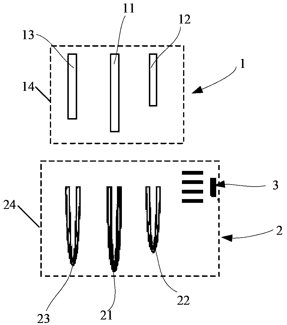
[0022] An embodiment of the present invention provides an electrical connector. The electrical connector includes an insulating shell and pins inside the insulating shell. An arc extinguishing grid is arranged inside the insulating shell around the pins. The arc extinguishing grid is used for The arc generated when the electrical connector is hot plugged is extinguished.

[0023] According to the electrical connector provided by the embodiment of the ...


PUM


Abstract

The embodiment of the invention discloses an electric connector and relates to the technical field of electrocommunication. According to the invention, the arc discharge problem of a present electric connector during the process of hot plug is solved. The electric connector provided by the invention comprises an insulation shell and pins arranged inside the insulation shell. An arc chute is arranged around the pins inside the insulation shell. The arc chute is used for extinguishing arc generated during hot plug of the electric connector. The electric connector is used for power supply and distribution of IT equipment.

Description

technical field [0001] The invention relates to the technical field of electronic communication, in particular to an electrical connector. Background technique [0002] At present, a large number of commercial IT equipment generally use UPS (uninterrupted power supply) for power supply and distribution. UPS systems use AC power, while IT equipment (servers, networks, storage devices) consume DC power, so it is necessary to Converting AC power to DC power and then converting DC power to AC power for delivery to computer equipment wastes 10 to 20 percent of the electrical energy. [0003] Compared with UPS power supply and distribution mode, high voltage direct current HVDC (High Voltage Direct Current) power supply and distribution has obvious advantages in terms of energy saving and reliability. Therefore, in the current IT equipment room, it has gradually become a trend for IT equipment to evolve from the traditional UPS power supply and distribution architecture to the HV...

Claims


Application Information

Patent Timeline
Patent Type & Authority Applications(China)
IPC IPC(8): H01R13/53
CPCH01R13/53
Inventor 朱洋肖高涛肖志明宋敏
Owner HUAWEI TECH CO LTD
Why Eureka
Try Eureka