Cooling structure of permanent magnet motor

A cooling structure, permanent magnet motor technology, applied in the direction of the casing/cover/support, electrical components, electromechanical devices, etc., can solve the problems of lowering the insulation level of the motor, lowering the usage rate, and high surface temperature of the motor housing, and reducing the heat loss, ensure permanence, provide work efficiency effects

Active Publication Date: 2014-10-29
SHANGHAI HANBELL PRECISE MASCH CO LTD
View PDF7 Cites 0 Cited by
  • Summary
  • Abstract
  • Description
  • Claims
  • Application Information

AI Technical Summary

Problems solved by technology

The main disadvantages are: 1. The surface temperature of the motor shell is high, and the heat generated by the rotor and the stator cannot be transferred well, which reduces the insulation level of the motor and shortens the service life of the motor. Rising 10, 12, 14 ℃, the life of the motor will be halved
[0008] 2. The poor cooling effect of the motor will directly affect the winding of the stator, reduce the utilization rate, and even cause burnout

Method used


Image

  • Cooling structure of permanent magnet motor
  • Cooling structure of permanent magnet motor

Examples


Embodiment Construction

[0015] Below in conjunction with accompanying drawing and specific embodiment the present invention is described in further detail:

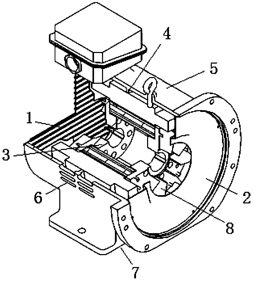
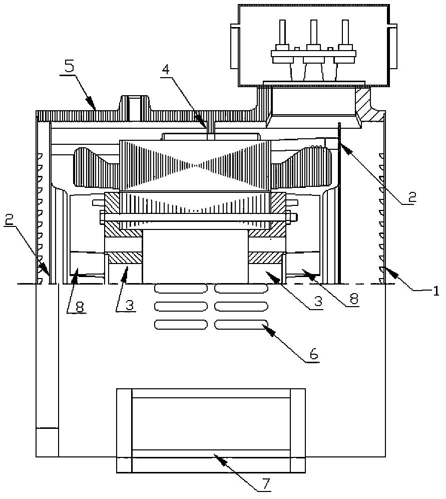
[0016] Depend on figure 1 , figure 2 It can be seen that the present invention includes: a motor housing 5; in the motor housing 5: a protective air suction plate 1, two inlet deflectors 2, a side air outlet 6, an air exhaust port 7, an annular retaining ring 4 and Two rotating part cover plates 3; the protective suction plate 1 is located at the rear end of the motor housing 5 to absorb the surrounding cooling air and prevent foreign matter from entering the motor housing; the two inlet deflectors 2 are respectively located at the front and rear ends of the motor housing 5, one of which is located inside the protective air suction plate 1, and two inlet deflectors 2 are used to absorb cooling air around the motor; the side air outlet 6 is located at the motor housing The side of the body 5 is used to generate wind pressure in the flow channe...


PUM


Abstract

The invention relates to a cooling structure of a permanent magnet motor. The cooling structure comprises a motor shell. In the motor shell, a protective wind-suction plate is positioned at the tail end of the motor shell and plays a role in sucking surrounding cooling air and preventing foreign matters from entering the motor shell; two entrance flow-deflectors are respectively positioned at front and back ends of the motor shell with one entrance flow-deflector positioned at the inner side of the protective wind-suction plate and the other entrance flow-deflector used for sucking cooling air around the motor; a side air-outlet is positioned at one side of the motor shell and is used for discharging heat inside the shell by the use of wind pressure generated in a channel of the motor shell out of the side air-outlet; an air outlet is positioned at the bottom of the motor shell and is used for discharging heat inside the motor shell under the action of wind pressure to ambient air; an annular retainer ring is positioned at the middle position of the motor shell and is used for isolating air mixed-flow between the front and back ends of the motor shell so as to prevent wind pressure from being not generated and reduce airflow loss; and two rotating-parts cover plates are positioned between the two entrance flow-deflectors and are used for fixing a rotor, wherein the two rotating-parts cover plates and fan blades form an integrated structure.

Description

technical field [0001] The invention relates to a permanent magnet motor, in particular to a cooling structure of the permanent magnet motor. Background technique [0002] The permanent magnet motor is used to determine the load, convert electrical energy into mechanical energy, and adopt high-performance permanent magnet excitation, which has the advantages of high speed, wide speed range, high power factor, high efficiency, wide high-efficiency area, and high efficiency under light load. , to achieve energy saving and high efficiency. [0003] The cooling structure of the permanent magnet motor in the prior art is to use an external fan for forced cooling. The main disadvantages are: 1. The surface temperature of the motor shell is high, and the heat generated by the rotor and the stator cannot be transferred well, which reduces the insulation level of the motor and shortens the service life of the motor. Rising 10, 12, 14 ℃, the life of the motor will be halved. [000...

Claims


Application Information

Patent Timeline
Patent Type & Authority Applications(China)
IPC IPC(8): H02K5/20
Inventor 盛昌国苏忠辉
Owner SHANGHAI HANBELL PRECISE MASCH CO LTD
Why Eureka
Try Eureka