A torque motor with positive magnetic spring stiffness

A torque motor and magnetic spring technology, applied in the field of rotary electro-mechanical converters, can solve problems such as difficult rotor stability, achieve the effects of reducing energy loss, reducing eddy current loss, and improving electromagnetic conversion efficiency

Active Publication Date: 2016-06-22
JIAXING NIYA OPTOELECTRONICS CO LTD
View PDF5 Cites 0 Cited by
  • Summary
  • Abstract
  • Description
  • Claims
  • Application Information

AI Technical Summary

Problems solved by technology

The existing torque motor has a small linear range and has a torque-angular displacement characteristic with negative magnetic spring stiffness. Under normal circumstances, it is difficult for the rotor to stabilize at the neutral position. A large mechanical return spring must be used to stabilize the rotor at the neutral position. It is generally used for small angle motors. Displacement control requirements

Method used


Image

  • A torque motor with positive magnetic spring stiffness
  • A torque motor with positive magnetic spring stiffness
  • A torque motor with positive magnetic spring stiffness

Examples


Embodiment Construction

[0024] The present invention will be further described below in conjunction with the accompanying drawings and embodiments, but not as a basis for limiting the present invention.

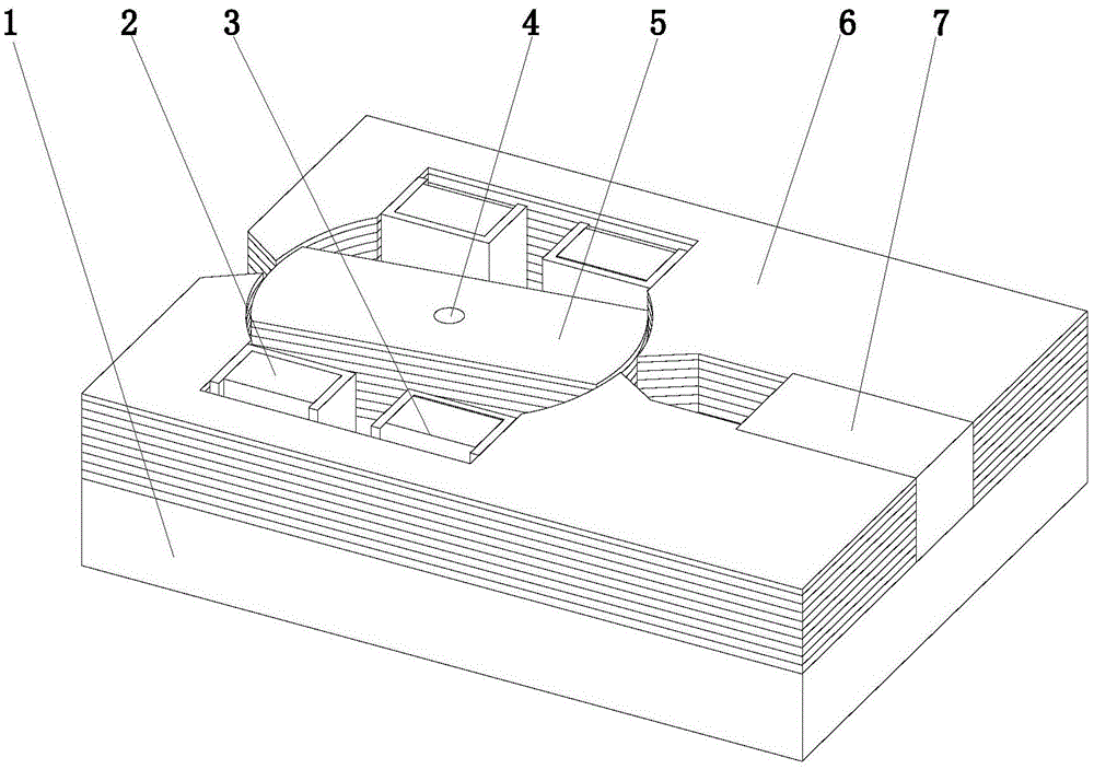
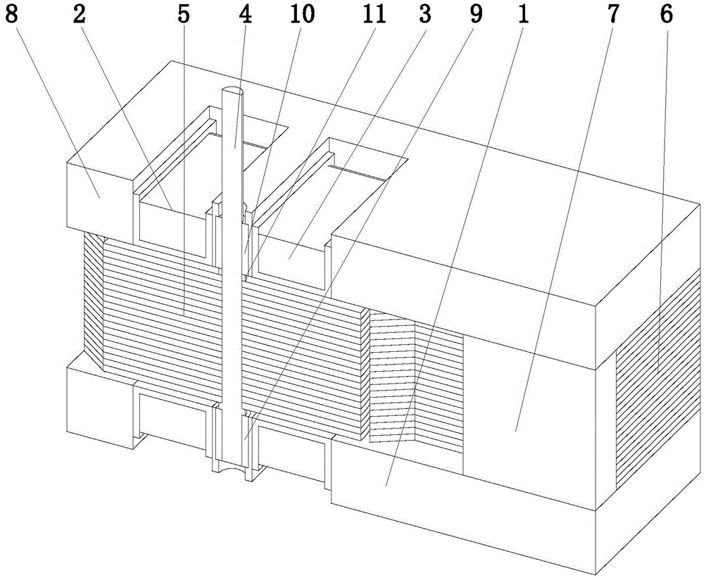
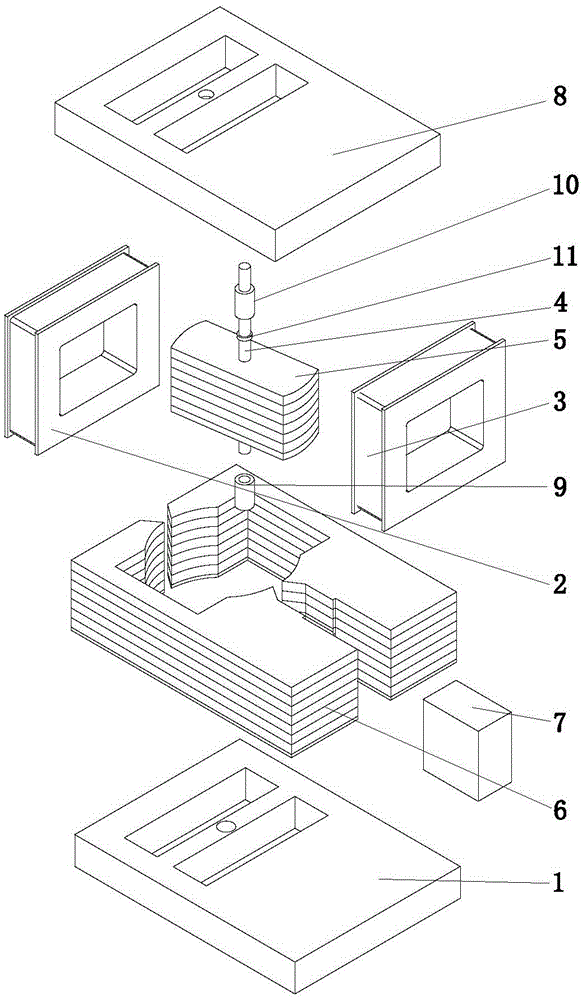
[0025] Example. A torque motor with positive magnetic spring stiffness, constructed as Figure 1-3 As shown, it includes bottom plate 1, coil winding A2, coil winding B3, output shaft 4, rotor 5, yoke iron 6, permanent magnet 7, top plate 8, bearing a9, bearing b10, sleeve 11, fixed on bottom plate 1 and top plate 8 The yoke 6 between is divided into a left yoke 61 and a right yoke 62, and the pole shoe surfaces of the left yoke 61 and the right yoke 62 form an isosceles trapezoidal air gap 12; one side of the left yoke 61 and the right yoke 62 The formed cavity is equipped with a permanent magnet 7, and two parallel coil windings A2 and B3 are installed in the cavity formed on the other side, and the inner cavity of the coil winding A2 and the coil winding B3 is fixed on the output shaft 4 The ro...


PUM


Abstract

The invention discloses a torque motor with positive magnetic spring stiffness, which consists of a bottom plate, a coil winding A, a coil winding B, an output shaft, a rotor, a yoke, a permanent magnet, a top plate, a bearing a, a bearing b, a sleeve, and a fixed The yoke between the bottom plate and the top plate is divided into a left yoke and a right yoke. A permanent magnet is installed in the cavity formed on one side of the left yoke and the right yoke, and two parallel magnets are installed in the cavity formed on the other side. Coil winding A and coil winding B are arranged, and the inner cavity of coil winding A and coil winding B is provided with a rotor fixed on the output shaft. The two ends of the rotor and the inner surface of the yoke form four-section annular air gaps, and the two ends of the output shaft are radially Bearing a and bearing b are respectively supported in the holes of the bottom plate and the top plate, and the axial direction is fixed by the sleeve and the shaft shoulder. The present invention has the torque-angular displacement characteristics of the positive magnetic spring stiffness within a certain angular displacement range, that is, the rotor does not need an external return spring, and can be stabilized at the neutral position under the action of the permanent magnet polarized magnetic field, and has good stability and wide angular displacement range. Large, compact structure, proportional control and other advantages, it is suitable for direct drive requirements of angular displacement proportional control in electromagnetic drive system.

Description

technical field [0001] The invention relates to a rotary electro-mechanical converter for angular displacement control in an electromagnetic drive system, especially a torque motor with positive magnetic spring stiffness. Background technique [0002] The torque motor is a rotary electro-mechanical converter. Its principle is to achieve differential control between the magnetic field generated by the control coil and the polarized magnetic field of the permanent magnet. The formed electromagnetic torque acts on the rotor and is converted into Angular displacement output. The existing torque motor has a small linear range and has a torque-angular displacement characteristic with negative magnetic spring stiffness. Under normal circumstances, it is difficult for the rotor to stabilize at the neutral position, and a large mechanical return spring must be used to stabilize it at the neutral position. It is generally used for small angle Displacement control requirements. Cont...

Claims


Application Information

Patent Timeline
Patent Type & Authority Patents(China)
IPC IPC(8): H02K24/00
Inventor 李勇申允德玄东吉成泰洪
Owner JIAXING NIYA OPTOELECTRONICS CO LTD
Why Eureka
Try Eureka