Minimum cutting thickness determination method of workpiece material
A technology of cutting thickness and determination method, applied in manufacturing tools, metal processing equipment, details of milling machine equipment, etc., can solve the problems of poor surface processing quality of workpieces, inability to determine the minimum cutting thickness for processing, etc., to improve processing accuracy and improve processing quality. , the effect of accurate calculation results
- Summary
- Abstract
- Description
- Claims
- Application Information
AI Technical Summary
Problems solved by technology
Method used
Image
Examples
specific Embodiment approach 1
[0022] The method for determining the minimum cutting thickness of the workpiece material in this embodiment, the determination method is specifically:
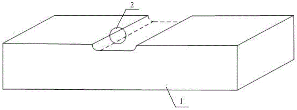
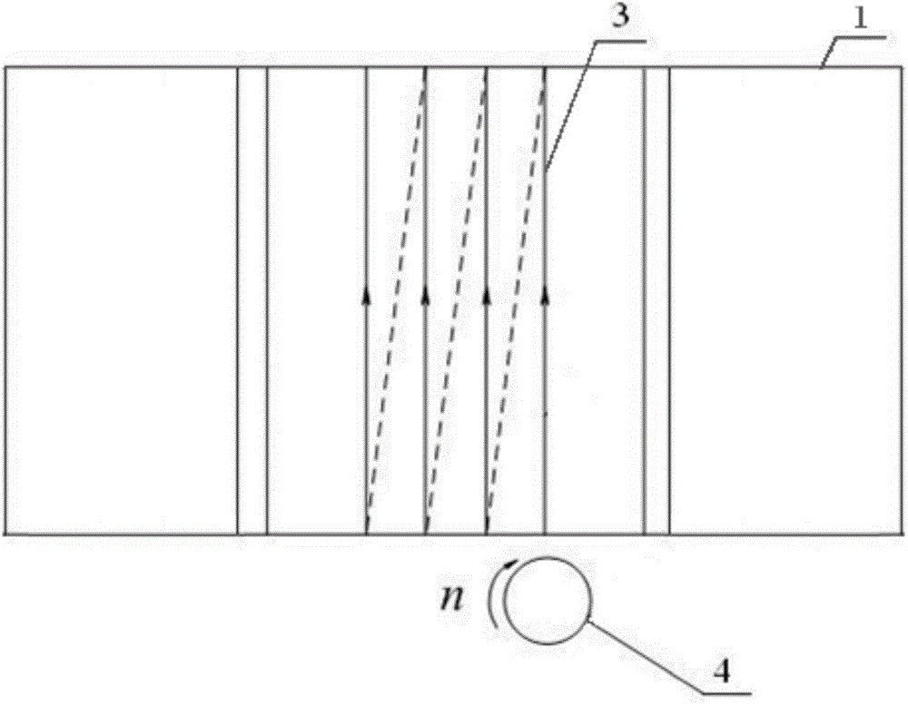
[0023] Step 1: Milling the workpiece material on a straight path on the workbench of the CNC milling machine;
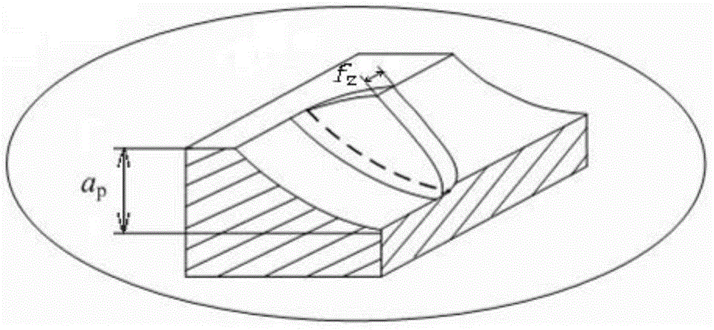
[0024] Step 2: Observing the milling marks of the workpiece material with an ultra-depth-of-field microscope, and according to the surface microscopic features of the milling marks, divide the area away from the tip of the tool to the tip of the tool when the tool rotates into a cutting area, a plowing area and a sliding area. Wipe the area, and measure the plowing area - the total length l of the sliding area;
[0025] Step 3: Using the total length l of the plowing area-sliding area obtained in step 2, calculate the minimum cutting thickness value h of the workpiece material D ,Specifically:
[0026] Step 3 1: After the first cutter tooth mills the workpiece material, a boundary line is formed on the surface, an...
specific Embodiment approach 2
[0034] The difference between this embodiment and specific embodiment one is:
[0035] In the method for determining the minimum cutting thickness of the workpiece material, the workpiece material used for milling is a cuboid.
[0036] Other steps and parameters are the same as those in Embodiment 1.
specific Embodiment approach 3
[0037] Specific embodiment three: the difference between this embodiment and specific embodiment one or two is:
[0038] In the method for determining the minimum cutting thickness of the workpiece material, the surface micro-topography of the cutting area in step 2 is characterized by a group of material residual ribs, and the width of the residual spacing between the material residual ribs is the same, and the The width of the remaining space is the feed per tooth value of the tool in question.
[0039] Other steps and parameters are the same as those in Embodiment 1 or Embodiment 2.
PUM
 Abstract
Description
Claims
Application Information
 - R&D
- Intellectual Property
- Life Sciences
- Materials
- Tech Scout
- Unparalleled Data Quality
- Higher Quality Content
- 60% Fewer Hallucinations
Browse by: Latest US Patents, China's latest patents, Technical Efficacy Thesaurus, Application Domain, Technology Topic, Popular Technical Reports.
© 2025 PatSnap. All rights reserved.Legal|Privacy policy|Modern Slavery Act Transparency Statement|Sitemap|About US| Contact US: help@patsnap.com


