The Determination Method of Minimum Cutting Thickness of Workpiece Material

A technology of cutting thickness and determination method, which is applied in the direction of manufacturing tools, metal processing equipment, milling machine equipment details, etc., can solve problems such as the inability to determine the minimum cutting thickness for processing, and poor processing quality of workpiece surface, so as to improve processing accuracy and improve processing quality , The effect of simple measurement process

Inactive Publication Date: 2016-12-07
HARBIN UNIV OF SCI & TECH
View PDF1 Cites 0 Cited by
  • Summary
  • Abstract
  • Description
  • Claims
  • Application Information

AI Technical Summary

Problems solved by technology

[0003] The purpose of the present invention is to solve the problem that the minimum cutting thickness of the workpiece cannot be determined when the existing tool cuts the workpiece material, resulting in poor processing quality of the workpiece surface, and proposes a method for determining the minimum cutting thickness of the workpiece material

Method used


Image

  • The Determination Method of Minimum Cutting Thickness of Workpiece Material
  • The Determination Method of Minimum Cutting Thickness of Workpiece Material
  • The Determination Method of Minimum Cutting Thickness of Workpiece Material

Examples


specific Embodiment approach 1

[0022] The method for determining the minimum cutting thickness of the workpiece material in this embodiment, the determination method is specifically:

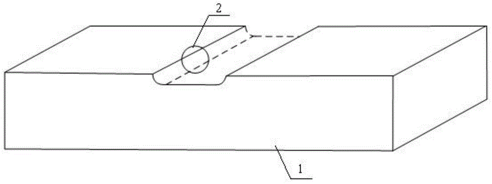
[0023] Step 1: Milling the workpiece material on a straight path on the workbench of the CNC milling machine;

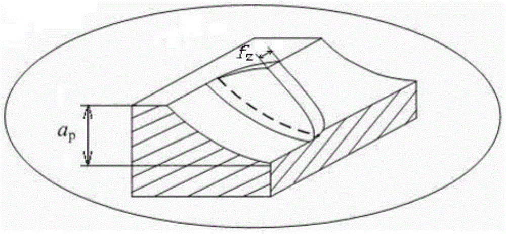
[0024] Step 2: Observing the milling marks of the workpiece material with an ultra-depth-of-field microscope, and according to the surface microscopic features of the milling marks, divide the area away from the tip of the tool to the tip of the tool when the tool rotates into a cutting area, a plowing area and a sliding area. Wipe the area, and measure the plowing area - the total length l of the sliding area;

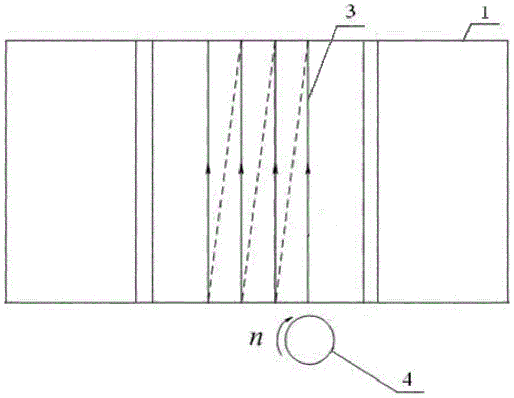
[0025] Step 3: Using the total length l of the plowing area-sliding area obtained in step 2, calculate the minimum cutting thickness value h of the workpiece material D ,Specifically:

[0026] Step 3 1: After the first cutter tooth mills the workpiece material, a boundary line is formed on the surface, an...

specific Embodiment approach 2

[0034] The difference between this embodiment and specific embodiment one is:

[0035] In the method for determining the minimum cutting thickness of the workpiece material, the workpiece material used for milling is a cuboid.

[0036] Other steps and parameters are the same as those in Embodiment 1.

specific Embodiment approach 3

[0037] Specific embodiment three: the difference between this embodiment and specific embodiment one or two is:

[0038] In the method for determining the minimum cutting thickness of the workpiece material, the surface micro-topography of the cutting area in step 2 is characterized by a group of material residual ribs, and the width of the residual spacing between the material residual ribs is the same, and the The width of the remaining space is the feed per tooth value of the tool in question.

[0039] Other steps and parameters are the same as those in Embodiment 1 or Embodiment 2.


PUM


Abstract

The invention relates to a minimum cutting thickness determination method of a workpiece material. At present, a theoretical analysis method during the processing of obtaining the minimum cutting thickness value of a workpiece material is tedious and has poor applicability, and a calculation result obtained is not accurate enough. The method comprises the following steps: milling trace of a workpiece material is observed under a super field-depth microscope, the surface is divided into a cutting area, a ploughing area and a rubbing area, and the total length l of the ploughing area-the rubbing area is measured; an intersection A of an interface of the ploughing area-the cutting area and a boundary line between a first cutter tooth and the surface of the workpiece is taken, central positions of the first cutter tooth and a second cutter tooth of the cutter starting to cut into the workpiece material are taken as points O1 and O2, a coordinate system is established with the point O1 as the origin of coordinates, a cutting cross section perpendicular to XO1Y is made by crossing the point O2 and the point A, and a projection point O1' of the point O1 on the section is obtained; a vertical line of XO1Y is made by crossing the point A, an intersection of the vertical line and the outline of the lower end of the cutting cross section is a point B, an intersection of O2B and the outline of the upper end of the cutting cross section is a point C, and hD=R-|O2C| is calculated in a triangle O2CO1' by the cosine law. The method is used for determining the minimum cutting thickness of a workpiece material during processing of a cutter.

Description

technical field [0001] The invention relates to a method for determining the minimum cutting thickness of a workpiece material. Background technique [0002] Cutting tools will have a certain cutting edge blunt circle radius in the manufacturing process. Due to the existence of the cutting edge blunt circle radius, there is a minimum cutting thickness of the material in the processing process. When the cutting thickness in actual processing is less than the minimum cutting thickness of the processed material When the thickness is too high, it will cause the contact between the tool and the workpiece mainly in the form of friction but cannot be cut normally, which will seriously affect the surface quality and accuracy of the processed workpiece, and even cause damage to the tool and workpiece, which should be avoided in actual processing. When other cutting parameters are determined in the cutting process, the minimum cutting thickness of the workpiece material determines the...

Claims


Application Information

Patent Timeline
Patent Type & Authority Patents(China)
IPC IPC(8): B23C3/00
Inventor 刘献礼马晶岳彩旭张安山刘强
Owner HARBIN UNIV OF SCI & TECH
Why Eureka
Try Eureka