
Cutting and trimming machine for plastic pipes

A technology of plastic pipes and trimming machines, which is applied in metal processing and other directions, and can solve the problems of entering the interior of machines such as motors, increasing manufacturing and production costs, and troublesome operation

Active Publication Date: 2014-11-05
YONGGAO CO LTD
View PDF6 Cites 17 Cited by
  • Summary
  • Abstract
  • Description
  • Claims
  • Application Information

AI Technical Summary

Problems solved by technology

The existing plastic pipe cutting machine adopts a circular track in the frame, and a sawtooth disc is set on the circular track. The sawtooth disc is driven by a motor to rotate, and at the same time revolves around the pipe on the circular track. The disadvantages of this structure cutting machine Is: 1. Use the sawtooth disc to cut the plastic pipe, the sawtooth will rub against the plastic pipe, the noise will be loud, and a large amount of plastic shavings and dust will be generated, which requires manual cleaning from time to time, and the plastic shavings and dust may also enter the motor and other machines Inside, it affects its normal operation; 2. There is no trimming device, so that there are flaws and unevenness in the cut of the plastic pipe, which affects the appearance of the product, and affects the degree of fit and sealing performance of the end of the product during assembly, so it must be placed separately Trimming on the trimming machine is cumbersome to operate, reduces production efficiency, and increases labor intensity of workers
And the existing cutting machine is installed on the frame and fixed, and the frame only supports and fixes the whole cutting machine. When the cutting machine cuts the plastic pipe, the cut plastic pipe is extruded from the back. The pipe moves forward under the action of the driving force, and the other end is supported by the manipulator to move forward and transported to the collection box. The disadvantages of this structure are: the manipulator has a complex structure, high power consumption, and increases manufacturing and production costs.

Method used


Image

  • Cutting and trimming machine for plastic pipes
  • Cutting and trimming machine for plastic pipes
  • Cutting and trimming machine for plastic pipes

Examples


Embodiment Construction

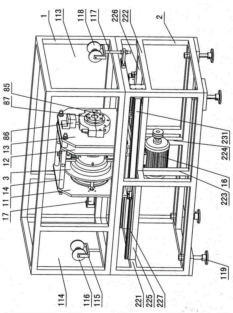
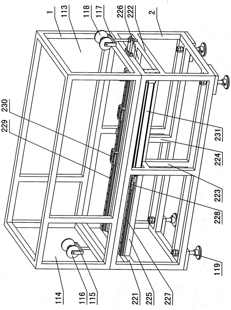
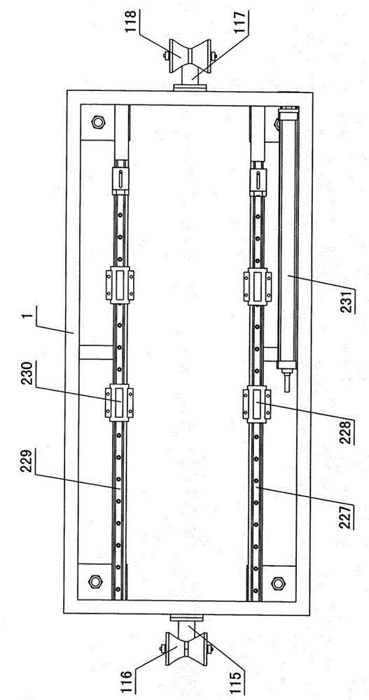
[0018] The invention relates to a cutting and trimming machine for plastic pipes, such as figure 1 — Figure 11As shown, it is characterized in that it includes a frame and a pipe material cutting and trimming mechanism, the frame includes an upper frame 1 and a lower frame 2, observation windows are respectively installed on the front and rear sides of the upper frame 1, and the left and right sides of the upper frame Side is left input port 113 and right output port 114 respectively, and left roller bracket 115 is installed in the left input port, and left roller bracket 116 is installed in the left roller bracket, and left roller through pin and left roller bracket rotates and cooperates, and right roller bracket is installed in the right input port 117, the right roller 118 is installed in the right roller bracket, and the right roller is rotated and matched with the right roller bracket through a pin. The left side of the lower frame 2 is formed with a left crossbeam 221,...


PUM


Abstract

A cutting and trimming machine for plastic pipes comprises a frame and a pipe cutting and trimming mechanism. The frame comprises an upper frame and a lower frame, A front slide rail mounting rod and a rear slide rail mounting rod are mounted on the upper frame and the lower frame. A front slide rail and a rear slide rail are mounted on the front slide rail mounting rod and the rear slide rail mounting rod. A front slider and a rear slider rail are disposed on the front slide rail and the rear slide rail. The pipe cutting and trimming mechanism is disposed on the front slider and the rear slider. The pipe cutting and trimming mechanism comprises a left main plate, a middle main plate and a right main plate. A motor is mounted below a base plate. A left pipe clamp and a left pushing air cylinder are mounted outside the left main plate. A right pipe clamp is mounted outside the right main plate. A left hobbing cutter cylinder bearing, a cutter holder push plate, a cutting feeding rack, a hobbing cutter cylinder and a right hobbing cutter cylinder bearing are disposed between the left main plate and the middle main plate. An upper mounting rod, a lower mounting rod and a cutter feeding rack slide rail are disposed on the hobbing cutter cylinder. A pipe cutting device is mounted on the upper mounting rod. A pipe trimming device is mounted on the lower mounting rod. The cutter feeding rack which contacts with the cutter holder push plate is disposed outside the hobbing cutter cylinder. An upper fixing rod and a lower fixing rod are disposed on the cutter feeding rack. A hobbing cutter guide rack matched with the pipe cutting device is disposed on the upper fixing rod. A roller guide rack matched with the pipe trimming device is mounted on the lower fixing rod. A belt pulley connected with a motor shaft through a belt is disposed between the middle main plate and the right main plate.

Description

technical field [0001] The invention relates to a machine for processing plastic pipes, in particular to a cutting and trimming machine for plastic pipes. Background technique [0002] After the plastic pipe extruder continuously extrudes the plastic pipe, according to the required length of the plastic pipe, install a cutting machine at the exit of the extruder to cut the plastic pipe, and finally put the cut plastic pipe into the collection box . The existing plastic pipe cutting machine adopts a circular track in the frame, and a sawtooth disc is set on the circular track. The sawtooth disc is driven by a motor to rotate, and at the same time revolves around the pipe on the circular track. The disadvantages of this structure cutting machine Is: 1. Use the sawtooth disc to cut the plastic pipe, the sawtooth will rub against the plastic pipe, the noise will be loud, and a large amount of plastic shavings and dust will be generated, which requires manual cleaning from time ...

Claims


Application Information

Patent Timeline
Patent Type & Authority Applications(China)
IPC IPC(8): B26D1/16B26D7/26B26D7/00B29C37/02
Inventor 张建均金梅达谢细三牟亦龙柳玉龙
Owner YONGGAO CO LTD
Learn More