Front floor assembly structure suitable for platform vehicle type

A front floor assembly and front floor technology, which is applied to the superstructure, superstructure sub-assemblies, vehicle components, etc., can solve the disadvantages of generalization of front floor assembly components, extension of the research and development period of the front floor assembly, and installation of reinforcing plates. Unable to realize general problems, to achieve the effect of shortening the research and development cycle, improving the rigidity and strength of the vehicle, and having a simple structure

Active Publication Date: 2014-11-05
ZHEJIANG GEELY HOLDING (GROUP) CO LTD +1
View PDF6 Cites 16 Cited by
  • Summary
  • Abstract
  • Description
  • Claims
  • Application Information

AI Technical Summary

Problems solved by technology

When the body width of a remodeled vehicle needs to be increased, the front floor assembly can borrow fewer parts, mainly the door sill, central tunnel (split type), and longitudinal beams, while the front seat beam cannot be borrowed; when the shifter, When components such as the handbrake need to be replaced, due to structural limitations, the installation of the reinforcement plate cannot be used universally and needs to be redeveloped, which is not conducive to the universalization of the front floor assembly components
In the development of new cars and remodeled cars, the front floor assembly of non-platform models is likely to prolong the development cycle and increase the manufacturing cost

Method used


Image

  • Front floor assembly structure suitable for platform vehicle type
  • Front floor assembly structure suitable for platform vehicle type
  • Front floor assembly structure suitable for platform vehicle type

Examples


Embodiment Construction

[0025] The present invention will be further described below in conjunction with the embodiments shown in the accompanying drawings.

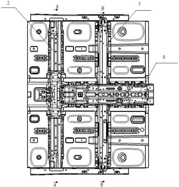
[0026] Such as Figure 1 to Figure 4 As shown, the present invention provides a front floor assembly structure suitable for platform vehicles, including left and right floor bodies 10, a front floor frame assembly, a central channel assembly below the front floor frame assembly, and a front floor frame assembly Threshold assembly 9 on both sides.

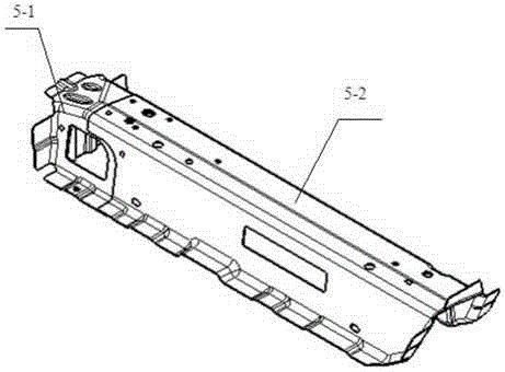
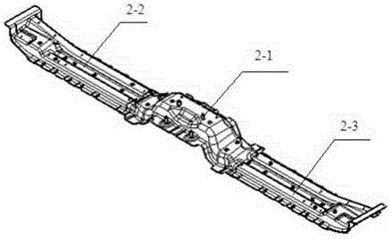
[0027] The central channel assembly includes a central channel 3 and a front underfloor beam 4 located below the rear end of the central channel 3. The front underfloor beam 4 is lapped on the central channel 3 and welded to it, such as figure 1 and figure 2 As shown, the left and right sides of the rear end of the central channel 3 are respectively provided with a front floor left longitudinal beam 6 and a front floor right longitudinal beam 7, and the front floor lower beam 4 is overlapped and a...


PUM


Abstract

The invention provides a front floor assembly structure suitable for a platform vehicle type. A central channel assembly of the front floor assembly structure comprises a central channel and a front floor lower cross beam located below the rear end of the central channel. A front floor framework assembly comprises two front seat front cross beams, a front seat rear cross beam and a central channel reinforcing plate, wherein the two front seat front cross beams are arranged on the left side and the right side of the front end of the central channel reinforcing plate and respectively comprise a front seat cross beam installation plate and a front seat cross beam, and the front seat cross beam installation plates are connected with the front seat cross beams. The front seat rear cross beam is arranged at the tail of the central channel reinforcing plate and comprises a middle section cross beam, a left section cross beam and a right section cross beam, and the middle section cross beam is arranged on the central channel reinforcing plate in a lap joint mode. Due to the design of the front seat front cross beam, the front seat rear cross beam and the central channel, a vehicle body platform part is constructed on the front floor assembly structure, the universality of components and the platformization of a front floor are achieved to the maximum, the demands for vehicle body front floor assemblies with different widths can be met, manufacturing cost can be saved to be maximum, and the developing cycle is shortened.

Description

technical field [0001] The invention belongs to the technical field of automobiles, relates to the field of vehicle structures, in particular to a front floor structure of a vehicle. Background technique [0002] Automotive products not only need to meet the differentiated requirements of different customers and countries in different regions, but also need to realize the maximum economic benefits of automakers. Platformization, as one of the important strategies to enable automakers to reduce costs and improve R&D efficiency, has been valued by automakers. The basic platform definition can be roughly divided into three forms: narrow sense, broad sense, and flexible platform development. Regardless of the platform definition, the front floor-related components are one of the core components. [0003] In the common front floor assembly structure, whether it is an integral type or a split type front floor, the generalization degree of components is relatively low. When the b...

Claims


Application Information

Patent Timeline
Patent Type & Authority Applications(China)
IPC IPC(8): B62D25/20
Inventor 戴锡锋闻培培陈君李国林李宏华吴成明冯擎峰
Owner ZHEJIANG GEELY HOLDING (GROUP) CO LTD
Why Eureka
Try Eureka