Air pressure heat storage type water heater
A water heater and thermal storage technology, applied in water heaters, fluid heaters, lighting and heating equipment, etc., can solve the problems of inconvenience and large space occupation, and achieve the goal of reducing energy consumption, balancing internal and external pressure, and reducing pressure. Effect
- Summary
- Abstract
- Description
- Claims
- Application Information
AI Technical Summary
Problems solved by technology
Method used
Image
Examples
Embodiment 1
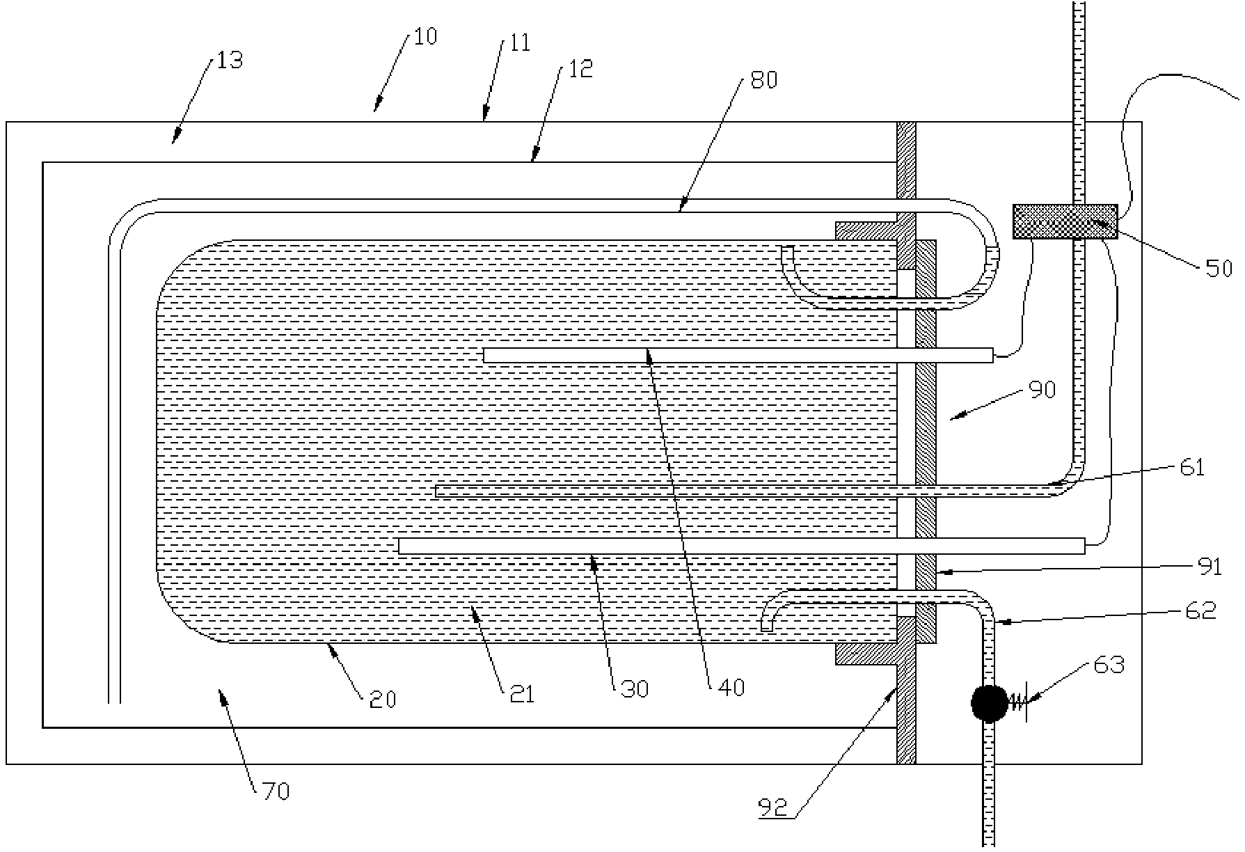
[0042] Such as figure 1 As shown, the housing 10 is formed by nesting an outer shell 11 and an inner shell 12 of different sizes. The outer shell 11 fits outside the inner shell 12, which are spaced apart from each other to form a cavity. The cavity can be evacuated by known technical means to form a vacuum insulation cavity 13, thereby improving the insulation effect through vacuum heat insulation. The outer shell 11 and the inner shell 12 can be integrally formed, or two independent parts can be connected together. When the outer shell 11 and the inner shell 12 are two independent parts, they can be connected together through various known detachable connectors, so as to facilitate disassembly and installation, and facilitate manufacturing. In this embodiment, the inner shell 12 is made of plastic material, which has the function of supporting the inner container. In other embodiments, the housing 10 can also be configured as a foam insulation structure, and a foam insula...
Embodiment 2
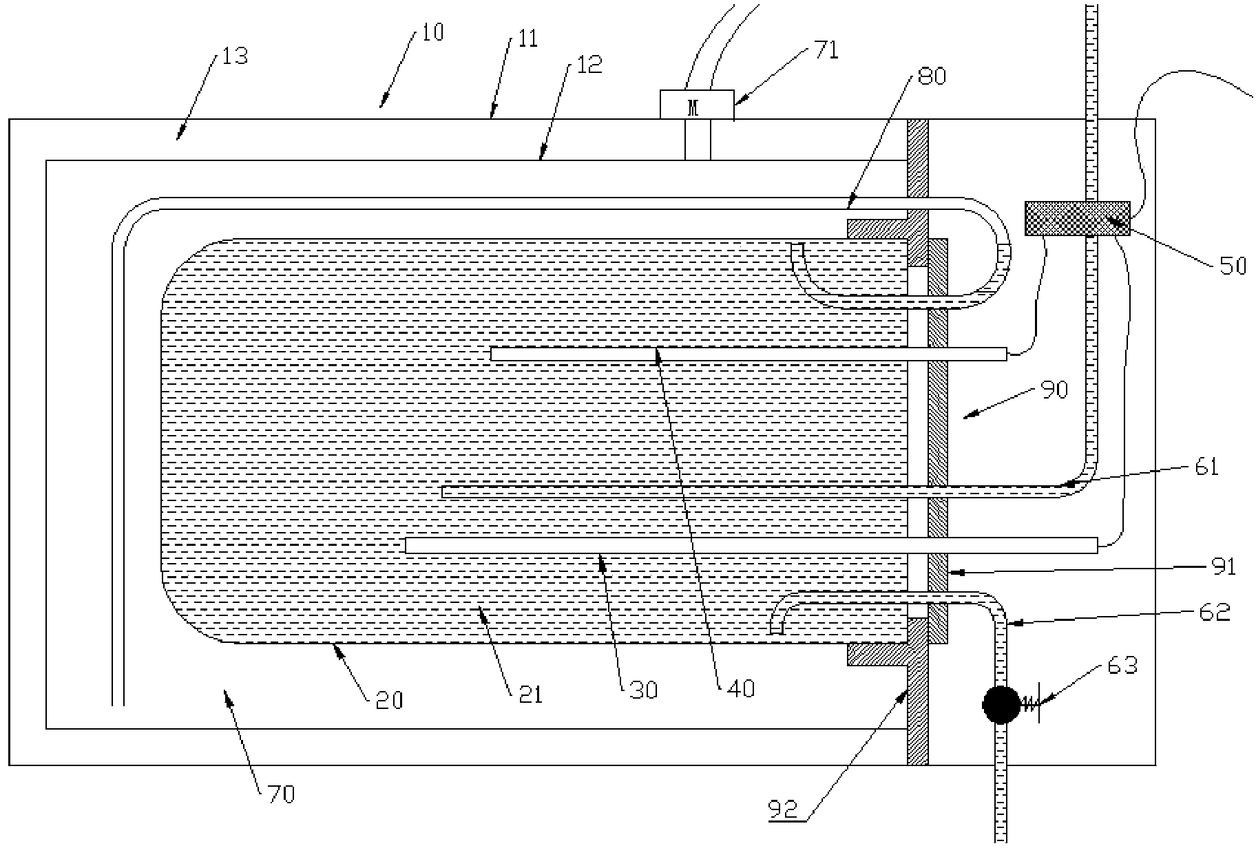
[0052] Such as figure 2 As shown, the basic structure of this embodiment is the same as that of Embodiment 1, the difference is that the gas storage chamber 70 in Embodiment 1 is pre-installed with compressed gas, but in this embodiment, the gas storage chamber 70 is not pre-installed There is compressed gas, on which a connection port is provided, and a pressurizing device 71 is provided outside or inside the housing 10, the pressurizing device 71 is connected through the connection port of the gas storage cavity 70, and is linked with the circuit control assembly 50 Connection, it injects gas into the gas storage chamber 70 when the water heater drains water to provide pressure for the water heater outlet, increasing the water output. The pressurizing device 71 can be a device such as a pressurizing pump. Further, the pressurizing device 71 can also be reversed to provide a suction force for the water inlet pipe 61 to increase the water inlet flow rate of the water inlet p...
Embodiment 3
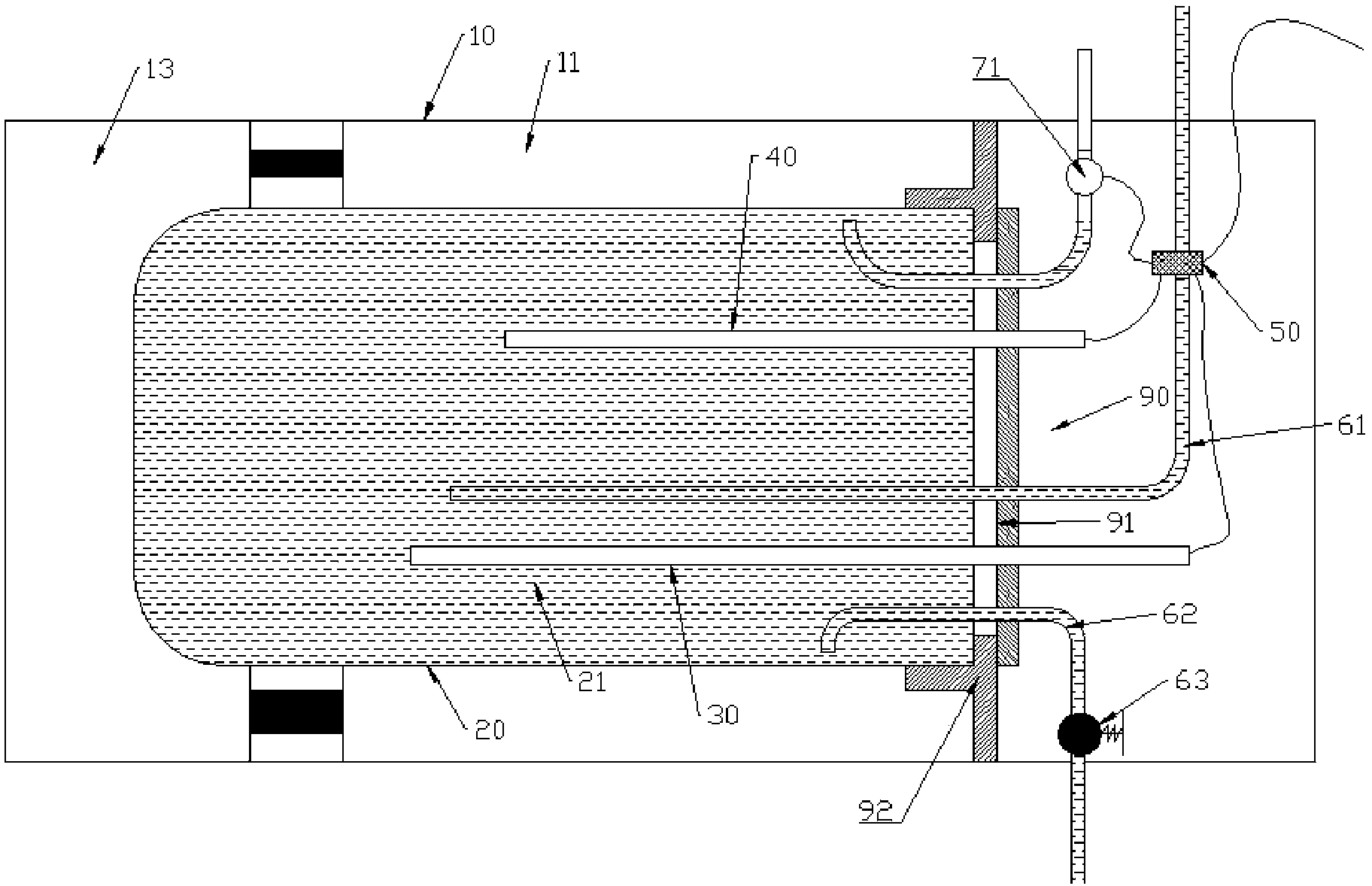
[0054] The basic structure of this embodiment is the same as embodiment 1, the difference is, as image 3 , Figure 4 As shown, the housing 10 is a single-layer housing 10, a vacuum insulation chamber is directly formed between the housing 10 and the water storage inner tank 20, and the gas storage chamber 70 is arranged in the water storage inner tank 20 Inside. The air storage cavity 70 and the water storage cavity 21 can be two functional areas of one cavity, or they can be two independent and interconnected cavities with the water storage cavity 21 . A certain amount of compressed gas can be pre-installed in the gas storage cavity 70 , and it is also connected to the pressurizing device 71 to inject gas inwardly when the water heater is used for discharging water.
PUM
 Abstract
Description
Claims
Application Information
 - R&D
- Intellectual Property
- Life Sciences
- Materials
- Tech Scout
- Unparalleled Data Quality
- Higher Quality Content
- 60% Fewer Hallucinations
Browse by: Latest US Patents, China's latest patents, Technical Efficacy Thesaurus, Application Domain, Technology Topic, Popular Technical Reports.
© 2025 PatSnap. All rights reserved.Legal|Privacy policy|Modern Slavery Act Transparency Statement|Sitemap|About US| Contact US: help@patsnap.com


