Bridge finite element model modifying method

A finite element and model technology, applied in the field of bridge finite element model correction, can solve the problems of low correction efficiency and correction accuracy of the correction method

Inactive Publication Date: 2014-11-05
NORTHEASTERN UNIV LIAONING
View PDF2 Cites 32 Cited by
  • Summary
  • Abstract
  • Description
  • Claims
  • Application Information

AI Technical Summary

Problems solved by technology

[0006] The purpose of the present invention is to provide a bridge finite element model correction method, which can effectively solve the problems in the prior art, especially the low correction efficiency and correction accuracy of the existing bridge finite element model correction method

Method used


Image

  • Bridge finite element model modifying method
  • Bridge finite element model modifying method
  • Bridge finite element model modifying method

Examples


Embodiment 1

[0171] Embodiment 1 of the present invention: a method for modifying a bridge finite element model, including the following steps:

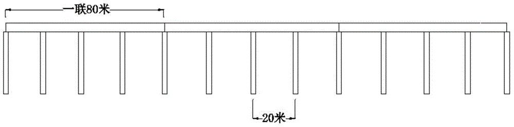
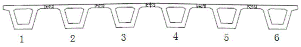
[0172] S1: Establish a solid finite element model of the full bridge through the general finite element calculation software ANSYS;

[0173] S2, using the uniform design method to make a correction to the physical finite element model of the full bridge; the number of experiments of the uniform design method is 3 to 5 times the number of factors;

[0174] S3: Use the uniform design method to select test points to generate a response surface, and use the response surface method to make secondary corrections to the solid finite element model of the full bridge;

[0175] S4, according to the revised model, judge whether the obtained stress loss or elastic modulus loss reaches the set warning value.

[0176] Wherein, the step S2 adopting the uniform design method to modify the physical finite element model of the full bridge once specifically includes:

[0177]...

Embodiment 2

[0194] Embodiment 2: A method for modifying a bridge finite element model, including the following steps:

[0195] S1: Establish a solid finite element model of the full bridge through the general finite element calculation software ANSYS;

[0196] S2, using the uniform design method to make a correction to the physical finite element model of the full bridge.

[0197] Wherein, the step S2 adopting the uniform design method to modify the physical finite element model of the full bridge once specifically includes:

[0198] X1, select the objective function Q(x) and the parameter variable X (such as m) to be corrected; the objective function Q(x) is specifically:

[0199] Q ( x ) = X i = 1 m γ i ( ϵ i ( X ) - ϵ ‾ i ϵ ‾ i ) 2

[0200] Among them, Q(x) is the objective function, r i Is the weight coefficient, ε i (X) is the strain value of the i-th point, Is the average value of i strains;

[0201] The erro...


PUM


Abstract

The invention discloses a bridge finite element model modifying method, which comprises the following steps that: 1, an entity finite element model of a whole bridge is built by universal finite element calculation software ANSYS; and 2, the entity finite element model of the whole bridge is subjected to primary modification by a uniform design method. The bridge finite element model modifying method has the following advantages that the uniform design method is used as a test optimization design method with obvious superiority, and the application of the uniform design method to the bridge structure finite element model modification is feasible; on the basis of the uniform design method, a more correct result can be found in a very short time by the uniform design method in the efficiency aspect, and the bridge large-scale finite element model modification efficiency is improved; a response surface method is used as a test design and mathematical statistics combined mathematical analysis method, and the application of the response surface method to the finite element model modification of a large-scale complicated bridge structure is feasible; and higher modification efficiency and higher modification precision can be ensured at the same time.

Description

Technical field [0001] The invention relates to a method for modifying a bridge finite element model, and belongs to the technical field of bridge finite element model modification. Background technique [0002] As a key point of transportation, bridges play an extremely important role in our daily lives. It is precisely because of the existence of bridges that the national highway and railway transportation network can be connected, forming a transportation system extending in all directions, and the importance of bridges to urban transportation is increasing day by day. With the rapid development of my country's economy in recent years, our country has made great achievements in bridge construction. At the same time, bridge construction is a project related to the safety of people's lives and property. Therefore, the health of bridges needs to be paid attention to. However, as the service life of the bridge increases, the internal structure and materials of the bridge itself w...

Claims


Application Information

Patent Timeline
Patent Type & Authority Applications(China)
IPC IPC(8): G06F17/50
Inventor 吴朝霞王立夫胡立朋邵元隆李俞呈樊红
Owner NORTHEASTERN UNIV LIAONING
Why Eureka
Try Eureka