Ku-waveband multi-channel switching receiving device and switching receiving method

A technology of a receiving device and a receiving method, applied in the field of radio frequency, can solve the problems of inapplicability of radio frequency microwave circuits, inability to precisely control alternate switching channels, high requirements for power supply, and phase consistency, and achieve the effect of avoiding excessive power consumption

Active Publication Date: 2014-11-05
SHANGHAI RADIO EQUIP RES INST
View PDF7 Cites 14 Cited by
  • Summary
  • Abstract
  • Description
  • Claims
  • Application Information

AI Technical Summary

Problems solved by technology

However, this device can only gate and sample voltage signals, and is not suitable for RF microwave circuits
[0004] Another channel selection device "new signal channel selection control circuit" (patent number: 03259742) controls channel gating through key switches, and cannot precisely control it to switch channels in turn at a certain frequency
[0005] At present, the number of channels of the Ku-band RF multi-channel switching receiver is generally 2, 4, 6, etc., and the most is 16 channels. The requirements for power supply and phase consistency are not high, but in some applications, the number of channels may reach Dozens or even hundreds, and the requirements for power supply and phase consistency are also very high
There is no such multi-channel switching receiving device at present

Method used


Image

  • Ku-waveband multi-channel switching receiving device and switching receiving method
  • Ku-waveband multi-channel switching receiving device and switching receiving method

Examples


Embodiment Construction

[0029] The specific embodiments of the present invention will be further described below in conjunction with the drawings.

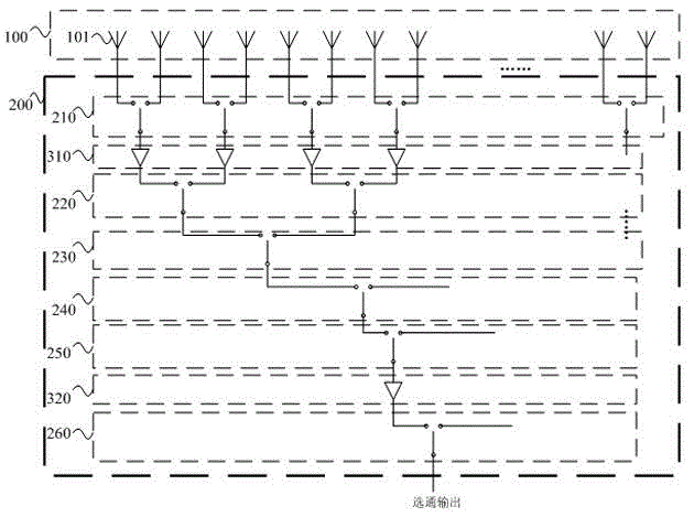
[0030] Such as figure 1 As shown, it is an embodiment of a Ku-band multi-channel switching receiving device. Its working bandwidth is 200MHz, the in-band gain consistency error is better than 3dB, and the in-band phase consistency is better than 2°. The device includes an antenna array 100 and a multi-channel switching array 200 electrically connected to the output end of the antenna array 100.

[0031] In this embodiment, the antenna array 100 includes 64 antenna elements 101, and each antenna element 101 serves as a receiving channel for receiving Ku-band signals.

[0032] The multi-channel switching array 200 includes six levels of switch layers, which are: a first-level RF switch layer 210, a second-level RF switch layer 220, a third-level RF switch layer 230, and a fourth-level RF switch that are sequentially cascaded Layer 240, fifth-level radio frequen...


PUM


Abstract

The invention discloses a Ku-waveband multi-channel switching receiving device. The Ku-waveband multi-channel switching receiving device comprises an antenna array, a multi-channel switching array and a main control module, wherein the antenna array comprises a plurality of antenna array elements for receiving Ku waveband signals; the multi-channel switching array is connected with the output of the antenna array, and comprises a plurality of switching layers formed hierarchically; each hierarchy of switching layer comprises a plurality of shift switches; the shift switches of each hierarchy of switching layer are used for combining two paths of channels output by a higher hierarchy of switching layer into one path of channel for outputting; and the main control module is communicated with each shift switch respectively, and is used for selecting and controlling a part of channels in the multi-channel switching array to be opened or closed. Channels for receiving Ku-waveband radio frequency signals are gated through the multi-channel switching array, so that certain channels can be specified to be in open states according to a set switching frequency, and meanwhile the remaining channels are in closed states.

Description

Technical field [0001] The invention relates to the field of radio frequency technology, in particular to a Ku-band multi-channel switching receiving device and a switching receiving method. Background technique [0002] In the array antenna signal receiving system and the signal acquisition process, we hope that the antennas in the array will not be turned on or off at the same time, but the specific antenna element will be turned on or off according to our expectations. For example, for a linear array, we hope that the array will start to turn on the first element at a certain moment, turn off the current element at the next moment and turn on the next element at the same time, or specify certain channels to be turned on or off at a certain time. This needs to be achieved through a multi-channel switching matrix control. When the frequency of the received signal is very high, such as the Ku band, the insertion loss, gain control, channel consistency and power management of the...

Claims


Application Information

Patent Timeline
Patent Type & Authority Applications(China)
IPC IPC(8): H04B1/16
Inventor 陈潜张翔夏礼诺卢护林
Owner SHANGHAI RADIO EQUIP RES INST
Why Eureka
Try Eureka