Detection method of contamination of image pickup module and detection system

A camera module and detection method technology, applied in image communication, television, electrical components and other directions, can solve problems such as difficult to see, reduce production efficiency, reduce detection speed, etc., achieve convenient and direct observation, improve production efficiency, improve Detecting the effect of speed

Active Publication Date: 2014-11-05
GUANGDONG LITE ARRAY +1
View PDF5 Cites 35 Cited by
  • Summary
  • Abstract
  • Description
  • Claims
  • Application Information

AI Technical Summary

Problems solved by technology

Either way, the watermark-type dirt caused by relatively light dirt on the screen is more difficult to capture, easy to ignore, or directly judge wrong, reducing the quality of the output module
At the same time, it is difficult to see this kind of relatively light watermark dirt directly with the naked eye, which will greatly reduce the detection speed, and the human eye is also prone to fatigue, reducing production efficiency
[0004] Under normal circumstances, the brightness difference between the relatively light watermark dirt and the adjacent area is generally only about 1 brightness difference, and due to the influence of other factors such as noise, power frequency interference, and vignetting when the module is working, the contact The brightness value of some pixels in the adjacent area is even the same as or lower than the brightness value of the watermarked dirty area (this is also an important factor that causes the software on the market to automatically judge the watermarked dirty area and is prone to errors)
The reason why it is difficult for software to automatically and accurately judge watermark-type dirt is because the dirt itself is relatively light, and due to the influence of various other factors when the module is working, the brightness difference between watermark-type dirt and adjacent areas is very large. Not obvious, at the same time, the difference between adjacent pixels is blurred, and the dividing line cannot be defined, which is the fundamental reason why it is difficult to see with the naked eye

Method used


Image

  • Detection method of contamination of image pickup module and detection system

Examples


Embodiment

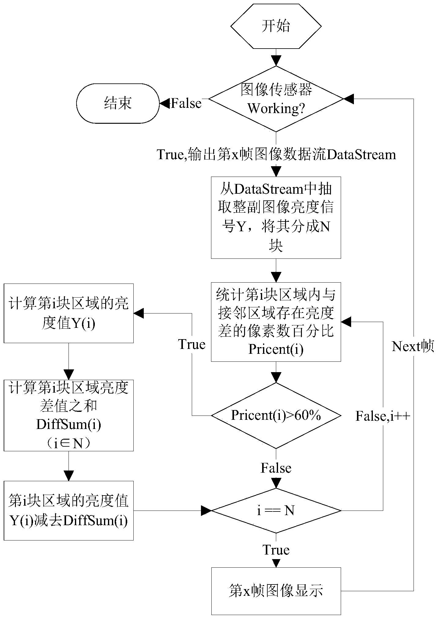
[0032] Example: see figure 1 , the present embodiment provides a camera module dirty detection method, which includes the following steps:

[0033] (1) A test background and an image processing module are set, and the pixel point percentage value is preset in the image processing module;

[0034] (2) prepare the camera module to be tested, and obtain the image data of the test background described in step (1) by the camera module to be tested;

[0035] (3) the image processing module extracts the brightness signal of the whole image from the image data obtained in step (2), and divides it into N block regions;

[0036] (4) Determine whether the number of pixels with a brightness difference from the adjacent area in the i (i∈N) block area accounts for the percentage of the number of pixels in the area, whether it is greater than the preset dirty judgment pixel percentage value in step (1) ;

[0037] (5) If in this area, the percentage of the number of pixels with brightness ...


PUM


Abstract

The invention discloses a detection method of contamination of an image pickup module. The detection method comprises the following steps of: setting a test background and an image processing module, and presetting a percentage value of preset pixel points in the image processing module; preparing an image pickup module to be detected, and obtaining image data of the test background; extracting a brightness signal of the whole image from the obtained image data by the image processing module, and dividing the brightness signal into N regions; judging whether a percentage of the number of the pixel points having the brightness difference with the adjacent region in the ith (i belongs to N) region in the number of the pixel points in the region is greater than a percentage value of the preset contamination judgment pixel points; and if the percentage of the number of the pixel points having the brightness difference with the adjacent region in the region is greater than the percentage value of the provided pixel points, judging that the region has contamination. The invention also discloses a system of implementing the method.

Description

technical field [0001] The invention relates to the field of camera module manufacturing, in particular to a method for detecting contamination of a camera module and a detection system for implementing the method. Background technique [0002] Due to the continuous improvement of the quality of life, people's visual requirements for images are constantly improving. No matter what kind of video products people use, they hope to output clear and realistic pictures. The clarity and fidelity of the picture requires not only the high resolution of the three-dimensional effect, but also some other interference factors that will greatly affect the quality of the picture, such as the effect of dirt in the module. Dirt will cause the image output by the module to become blurred, and even the slightest degree of dirt will reduce the clarity of the image to a certain extent. [0003] At present, there are two ways to detect the dirt of the module on the market: 1. Observation by dire...

Claims


Application Information

Patent Timeline
Patent Type & Authority Applications(China)
IPC IPC(8): H04N17/00
Inventor 沈振权舒伟平曹后平田野童小琴卢密方发清
Owner GUANGDONG LITE ARRAY
Why Eureka
Try Eureka