

Electromagnetic stirring apparatus, and continuous casting method
A technology of electromagnetic stirring and electromagnetic coils, which is applied in the field of electromagnetic stirring devices, can solve problems such as difficulty in forming a moving magnetic field and discontinuous penetration of electromagnetic force, and achieve the effect of suppressing equipment costs
Active Publication Date: 2014-11-05
NIPPON STEEL CORP
View PDF10 Cites 4 Cited by
- Summary
- Abstract
- Description
- Claims
- Application Information
AI Technical Summary
Problems solved by technology
[0012] However, when a plurality of molds with small cross-sections are provided between the disk-shaped electromagnetic coils, the magnetic flux component passing through the mold 4 becomes too strong because the interval L between the disk-shaped electromagnetic coils becomes narrow. , so that it is difficult to form a moving magnetic field, and a penetrating region where the electromagnetic force is discontinuous (refer to Figure 6B The deformation of the electromagnetic force at the inhomogeneous flow part of the)
Method used
View moreImage
Smart ImageViewing Examples

Examples
Embodiment
[0053] Hereinafter, examples performed to confirm the effects of the present invention will be described.
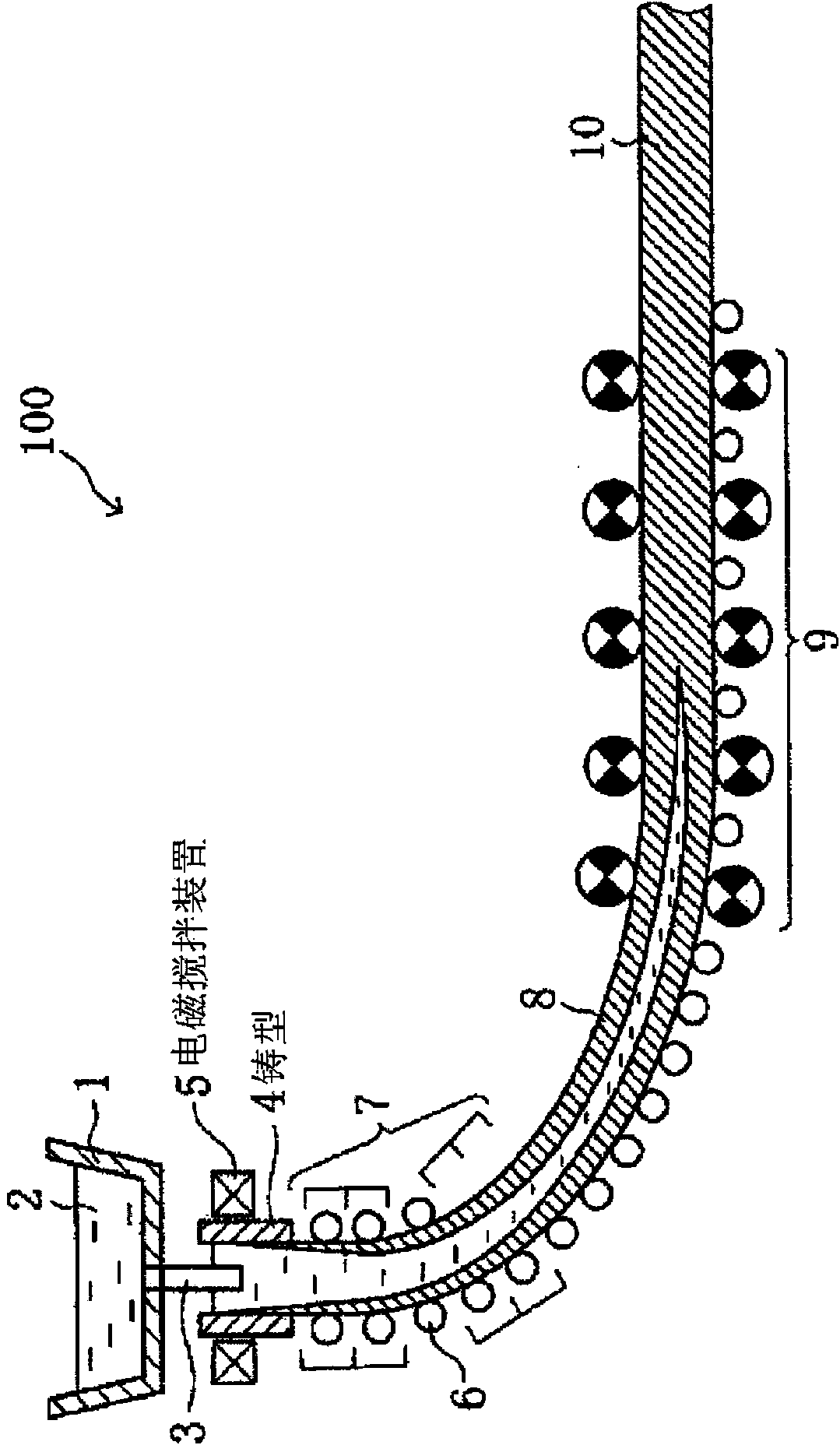
[0054] The present invention imparts electromagnetic force in the mold 4 by using the following electromagnetic stirring device 5, thereby making the molten steel flow uniformly, as a result, improving the internal quality of the cast sheet, wherein the width of the electromagnetic stirring device 5 configured in the casting direction is In the electromagnetic coils C1 and C2 of W, there is a position where a meniscus exists in a region sandwiched between an end surface on one end side in the casting direction and an end surface on the other end side.
Login to View More PUM
 Abstract
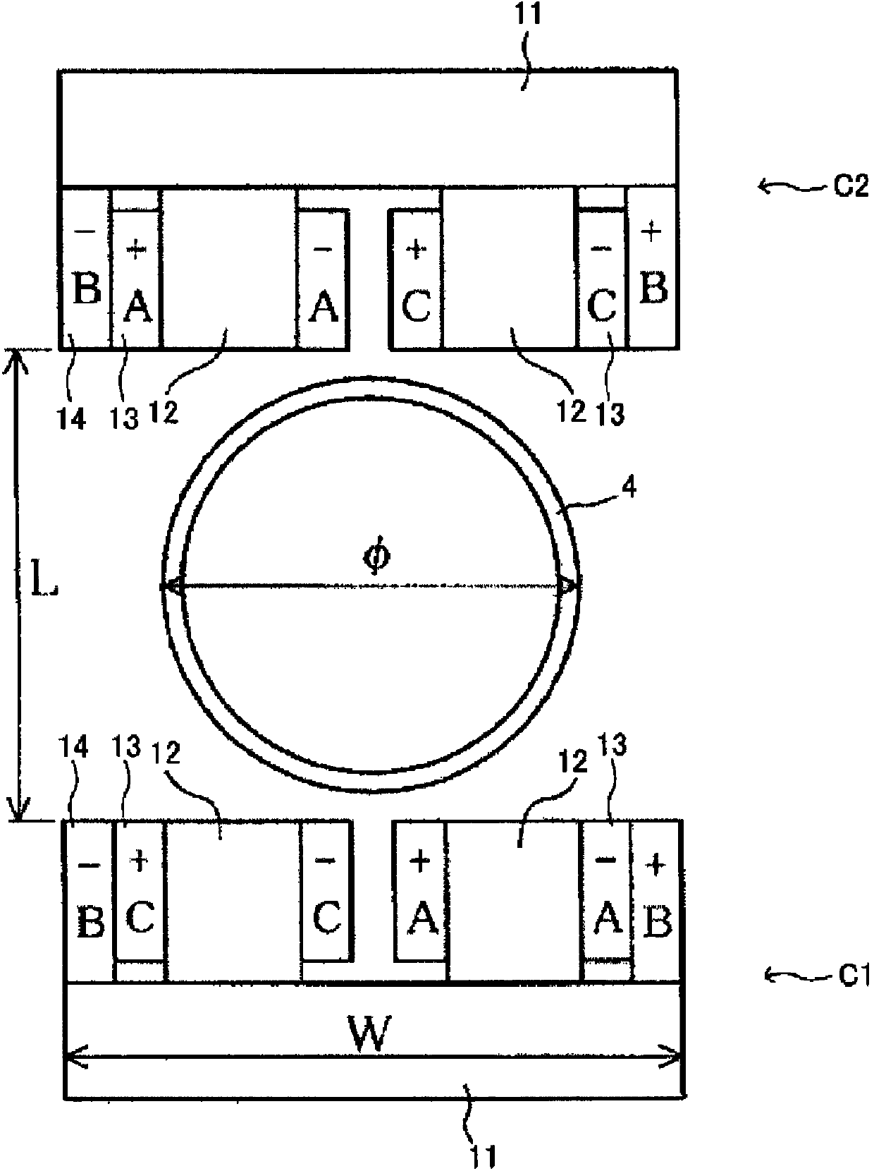
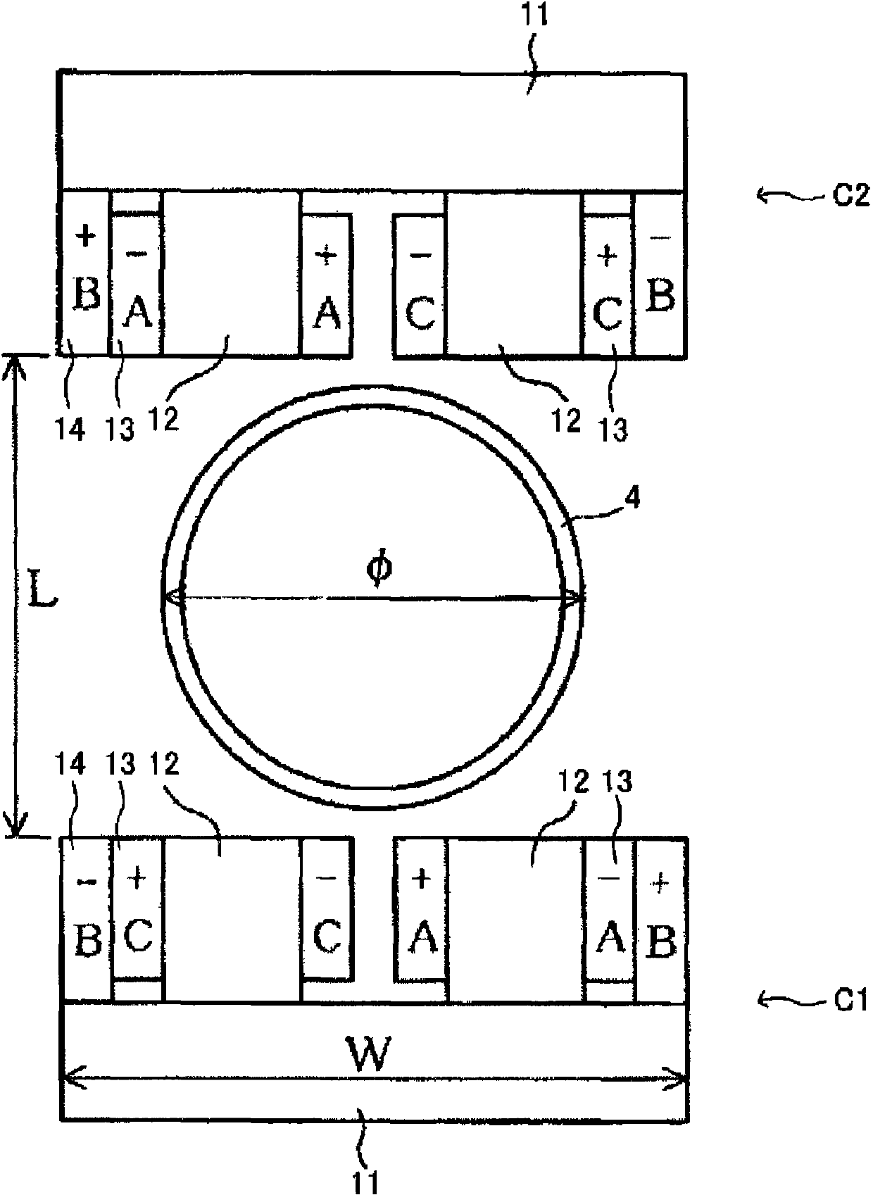
The main purpose of the present invention is to provide an electromagnetic stirring apparatus such that uniform electromagnetic force can be supplied to each mold. In an electromagnetic stirring apparatus (5) according to the present invention, two teeth portions (12) are disposed on cores (11) of a pair of electromagnetic coils (C1, C2) disposed across a mold (4), with inner windings (13) disposed on the outside of the teeth portions (12) and outer windings (14) disposed on the outside of the inner windings (13). The windings are supplied with currents A, B, and C with phase differences of 120º from a three-phase alternating current power supply. The directions of the currents in order from one end of the direction of casting to the other are -B, +C, -C, +A, -A, +B for the coil (C1) and -B, +A, -A, +C, -C, +B for the coil (C2) when the distance (L) between the coils (C1, C2) is not less than 500 mm, or -B, +C, -C, +A, -A, +B for the coil (C1) and +B, -A, +A, -C, +C, -B for the coil (C2) when the distance (L) is less than 500 mm. The mold disposed between the coils (C1, C2) satisfies n × phi < W, where n is the number of molds, phi is the outer size of each mold, and W is the width of the electromagnetic coil.
Description
technical field [0001] The present invention relates to an electromagnetic stirring device capable of controlling the uniform flow of molten steel in a mold for a single or multiple casting molds in a continuous casting device for small steel billets with a circular cross section or a rectangular cross section, and the use of the electromagnetic stirring device continuous casting method. Background technique [0002] Small steel billets with circular cross-section or rectangular cross-section become the raw materials of seamless steel pipes and section steels of various cross-sectional sizes through pipe making and rolling processes. Since seamless steel pipes and section steels have various product sizes and rolling processes are also different, the cross-sectional dimensions of the billet cast as the base material are also diverse. Therefore, pouring is performed with the number of molds corresponding to the production capacity. [0003] Here, among continuously cast sla...
Claims
Login to View More Application Information
Patent Timeline
 IPC IPC(8): B22D11/115B22D11/04
CPCB22D11/115B22D11/041B22D11/122
Inventor池田达彦冈田信宏林浩史山崎正弘
OwnerNIPPON STEEL CORP