Dryer for a textile product web

A drying machine and fabric technology, applied in the direction of progressive drying machine, drying machine, drying gas arrangement, etc., can solve the problems that the fresh air channel cannot be connected to the heat exchanger, lack of space, time-consuming and labor-intensive, etc.

Active Publication Date: 2014-11-05
TRUETZSCHLER GRP SE
View PDF6 Cites 9 Cited by
  • Summary
  • Abstract
  • Description
  • Claims
  • Application Information

AI Technical Summary

Problems solved by technology

A further disadvantage is the often time-consuming and labor-intensive retrofitting due to the lack of space and the fact that the fresh air duct cannot be connected to the heat exchanger
Since the dryers are located very close together in a series of different industrial technical units that process textile fabrics one behind the other, there is often no room for the subsequent installation of ducts for fresh air between the units

Method used


Image

  • Dryer for a textile product web
  • Dryer for a textile product web
  • Dryer for a textile product web

Examples


Embodiment Construction

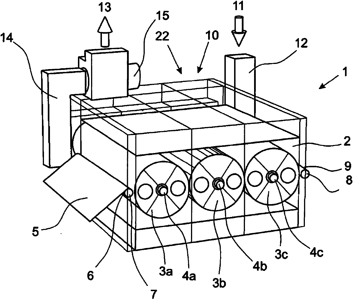
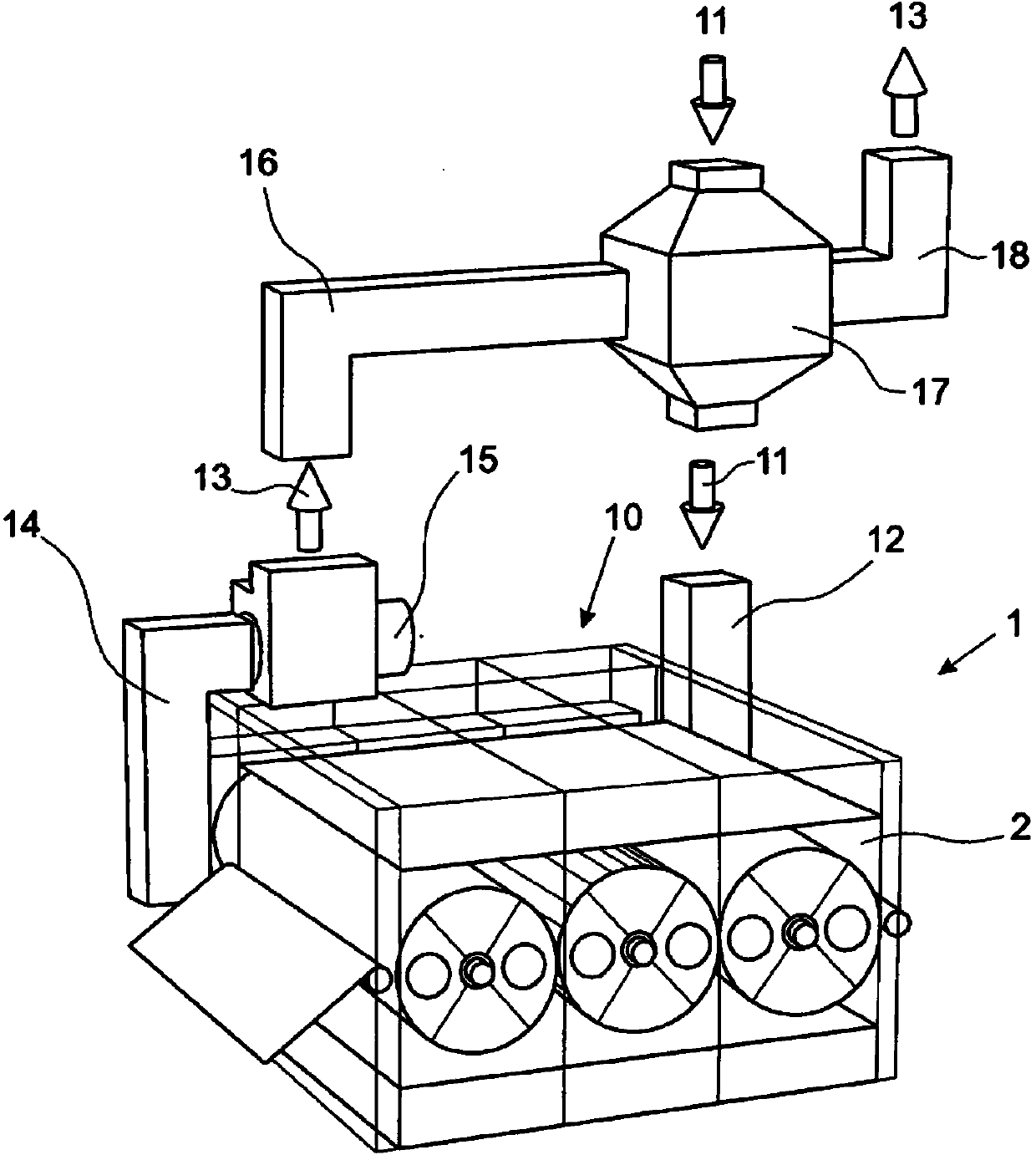
[0023] figure 1 The dryer 1 is shown in the form of a series dryer. Three rollers 3 a , 3 b , 3 c are arranged in succession and in series with their axes 4 a , 4 b , 4 c inside the drying chamber 2 . The fabric 5 is guided into the drying chamber 2 via the inlet 6 . The fabric 5 is guided via guide rollers 7 firstly below the first cylinder 3a, then above the second cylinder 3b and then below the third cylinder 3c. The web 5 is guided out of the drying chamber 2 via a guide roller 8 through an outlet 9 . During passage through the drying chamber 2 heated drying air is passed through the fabric 5 . Here, the drying air absorbs the moisture of the fabric 5 and is drawn through the interior of the cylinders 3a to 3c.

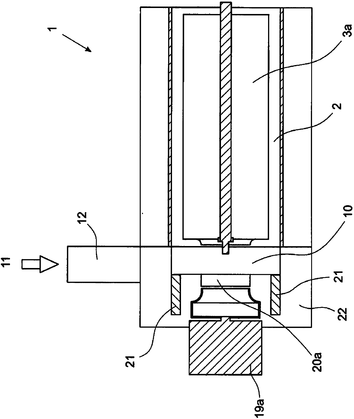
[0024] According to the invention, an additional chamber 10 is provided on the drying chamber 2 , into which a channel 12 for fresh air 11 and a channel 14 for exhaust air 13 open. The additional chamber 10 is formed completely separately and independently of...


PUM


Abstract

The invention relates to a dryer for a textile product web, comprising a dryer chamber (2) and having at least one drum (3a), which is arranged in the dryer chamber (2) and around which the product web (5) wraps at least partly, wherein heated drying air flows through the product web (5) and is led away via an interior of the drum (3a), and the dryer (1) has a separate additional chamber (10), via which fresh air (11) is led in and exhaust air (13) is led away.

Description

technical field [0001] The invention relates to a dryer for textile fabrics, and a method for drying textile fabrics. Background technique [0002] A wide variety of dryers are known for drying textile fabrics, in the housing of which one or more drums are arranged. The textile fabric is fed into the dryer via openings in the drying chamber in such a way that the fabric is wound around a large part of the circumference of the drum and then led out of the drying chamber. Usually, fresh air is also supplied via this opening, which is heated inside the drying chamber and mixed with the circulating air, so that it can absorb as high a proportion of moisture as possible. When winding the drum, a mixture of circulating air and fresh air flows through the fabric, at least partially absorbs the moisture from the fabric and is conducted again via the interior of the drum. A part of the volume flow is derived from this volume flow as exhaust air. In this case, the wet exhaust air i...

Claims


Application Information

Patent Timeline
Patent Type & Authority Applications(China)
IPC IPC(8): F26B13/16F26B21/02
CPCF26B13/16F26B21/02
Inventor 马库斯·波恩斯特凡·哈吉度
Owner TRUETZSCHLER GRP SE
Why Eureka
Try Eureka