Cable break prevention device for cable vehicle and using method thereof
An anti-breakage and cable technology, which is applied in the direction of vehicle components, transportation and packaging, circuits or fluid pipelines, etc., can solve the problems that the shaft and cable steel pipes are not suitable, difficult to replace, and large economic losses, etc., to reduce the axial and Circumferential fatigue damage, effect of prolonging service life
- Summary
- Abstract
- Description
- Claims
- Application Information
AI Technical Summary
Problems solved by technology
Method used
Image

Examples
Embodiment Construction
[0033] In order to make the object, technical solution and advantages of the present invention clearer, the implementation manner of the present invention will be further described in detail below in conjunction with the accompanying drawings.
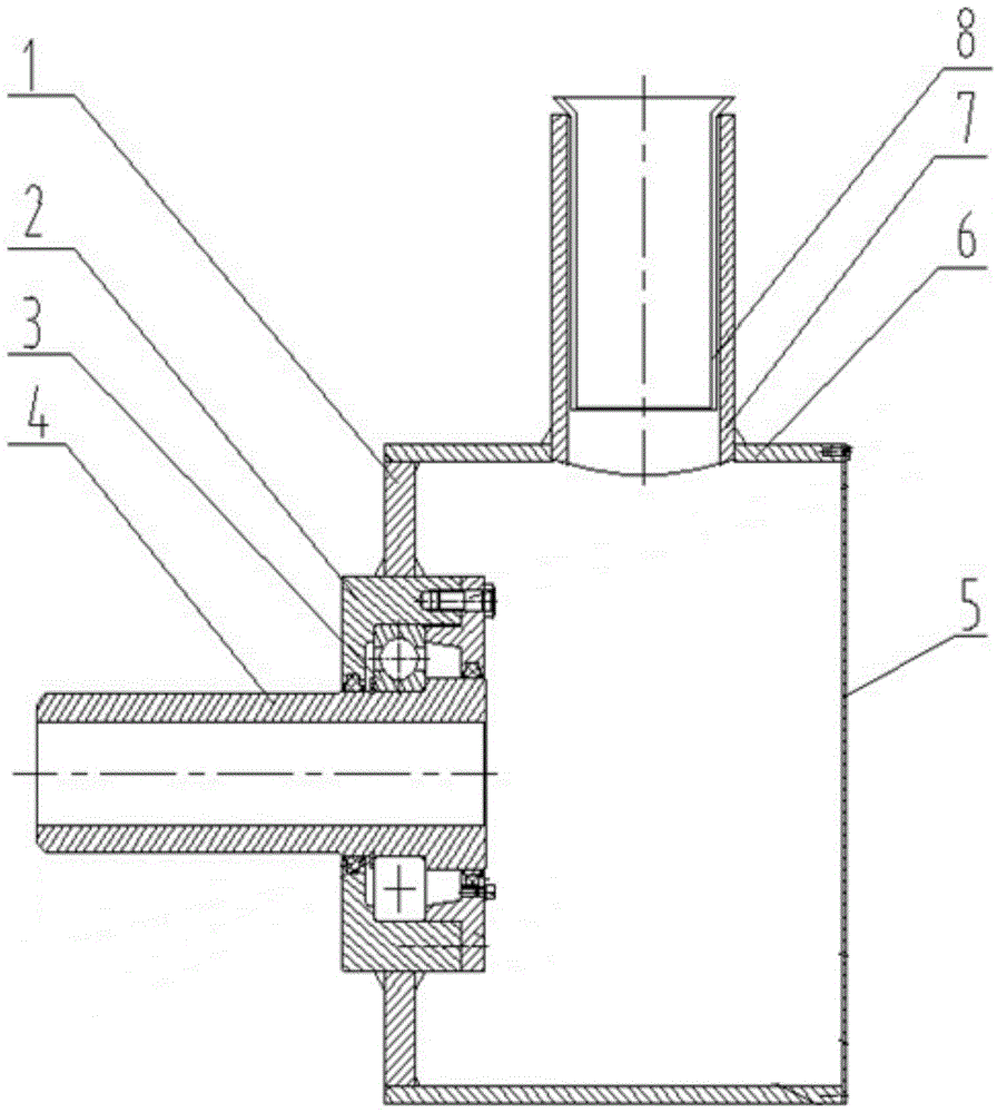
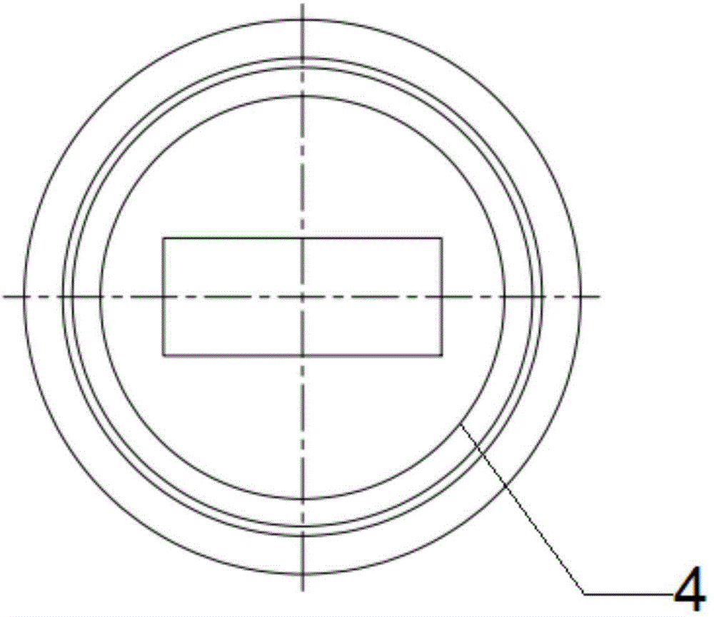
[0034] see figure 1 , a cable breakage prevention device for a cable vehicle, including a cylinder 6 that can accommodate cables, a support plate 1 is provided at one end of the cylinder 6, a bearing seat 2 is provided on the support plate 1, and a bearing 3 is installed in the bearing seat 2 , also includes the shaft 4 that cooperates with the bearing 3, such as image 3 As shown, the shaft 4 is provided with a channel communicating with the cylinder 6;
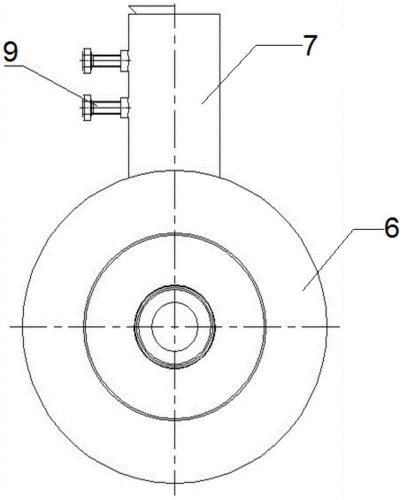
[0035] The side of the cylinder 6 is also provided with a cable steel pipe 7 communicating with the cylinder 6, the passage of the shaft 4, the cylinder 6 and the cable steel pipe 7 form a passage for cables to pass through.
[0036] The cable steel pipe 7 is provided with a fixed ...
PUM
 Abstract
Description
Claims
Application Information