Plantation type non-point pollution treatment ditch

A non-point source pollution and vegetation technology, applied in biological water/sewage treatment, multi-stage water/sewage treatment, water/sludge/sewage treatment, etc. Occupancy and other issues, to achieve the effect of reducing construction and maintenance management costs, flexible and rapid response

Inactive Publication Date: 2014-11-12
K C RIVERTECH
View PDF5 Cites 0 Cited by
  • Summary
  • Abstract
  • Description
  • Claims
  • Application Information

AI Technical Summary

Problems solved by technology

[0007] First, in the figure 1 In the osmotic treatment shown in the upper figure, a porous water channel such as a perforated pipe is used to guide the inflowing raw water to infiltrate the surrounding ground, and there is no need to replace the filter material 19, so it is not only easy to maintain and manage, but also can fully ensure the quality of water in the water channel. Therefore, it has the advantage of being able to respond to a sharp increase in the inflow, but there is a serious problem as follows: As the treatment flow increases, soil particles on the surrounding ground are caused during the infiltration of the treatment water. Erosion and ground weakening
[0008] exist figure 1 In the filtration treatment shown in the lower figure, the water channel is loaded with granular filter material 19 to guide the filtration and adsorption of pollutants. Since it is a structure in which the treated water is isolated from the surrounding ground, although the above-mentioned osmotic treatment can be prevented The treated soil particles are lost and the ground is weakened, but not only the filter material 19 must be replaced periodically, but also the filter material 19 occupies most of the cross-sectional area of ​​the waterway, so there is a problem that sufficient drainage function cannot be realized

Method used


Image

  • Plantation type non-point pollution treatment ditch
  • Plantation type non-point pollution treatment ditch
  • Plantation type non-point pollution treatment ditch

Examples


Embodiment Construction

[0036] Hereinafter, the detailed configuration and functions of the present invention will be described with reference to the drawings.

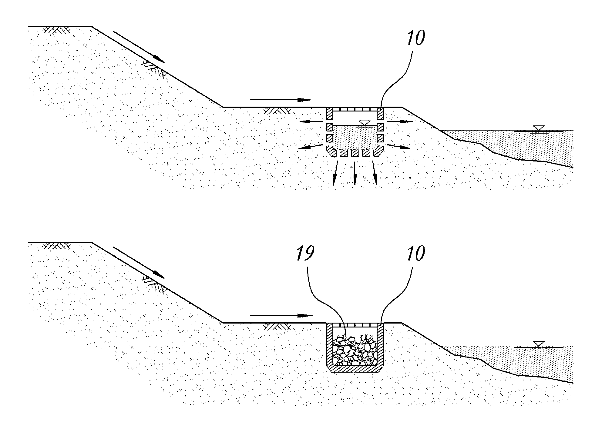
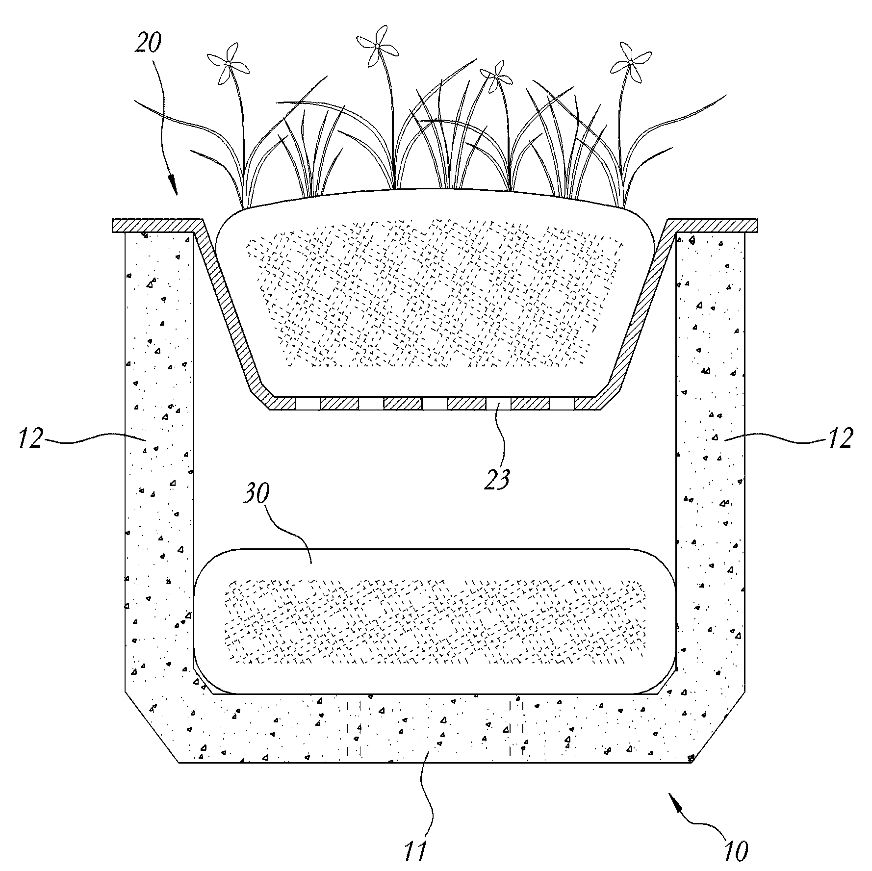
[0037] first, figure 2 and image 3 It is a partially cut-away exploded perspective view and a representative cross-sectional view respectively showing the appearance and structure of the lower permeable embodiment of the present invention. As shown in the figure, the lower permeable embodiment of the present invention is composed of the following parts: an open channel 10, which consists of The bottom plate 11 formed with a plurality of drain holes 13 and the side walls 12 at both sides of the bottom plate 11 are formed to allow water to flow in under rainfall; and the fiber bag 30, which is placed on the upper surface of the bottom plate 11, is formed by filling granular bodies inside a skin made of natural fibers.

[0038] That is, the bottom plate 11 of the open channel 10 is formed with a plurality of drainage holes 13 that penetrate...


PUM


Abstract

PURPOSE: A vegetation type non-point pollutant treating ditch is provided to effectively treat non-point pollutants without building a drainage way and a treatment facility. CONSTITUTION: A vegetation type non-point pollutant treating ditch comprises an open conduit (10), a vegetation board (20), and a fiber bag (30). The open conduit is formed with a bottom board (11) with a plurality of drainage holes and a sidewall (12) to allow rainfall effluent to flow in. The vegetation board is formed with a plurality of permeable holes (23), is joined to the top end of the open conduit, and is loaded with vegetation materials to vegetate. The fiber bag is arranged on the top surface of the bottom plate. The fiber bag is made of a natural fiber material filled with a granular material.

Description

technical field [0001] The present invention relates to a vegetation-type ditch as follows, which is composed of an open channel 10 that flows into the rainwater, etc., and a planting board 20 that is connected to the upper end of the open channel 10 and planted with plants, so as to treat non-point source pollution. A natural fiber fiber bag 30 filled with granules is built in the open channel 10, and drain holes 13 are formed on the bottom plate 11, or a guide frame 40 arranged with a plurality of gently inclined drain rods 41 is built in the open channel 10, and the side The wall 12 forms a drainage hole 13, so that the inflowing raw water as the treatment object passes through the plants and vegetation materials planted on the upper part of the open channel 10 for primary treatment, and when the initial rainfall flows into the drain, the inflow water is guided to penetrate to the surrounding areas of the open channel 10 On the ground, when the inflow increases due to conti...

Claims


Application Information

Patent Timeline
IPC IPC(8): C02F9/02
CPCC02F3/32C02F2103/26E03F3/046E03F5/14
Inventor 李明勋
Owner K C RIVERTECH
Why Eureka
Try Eureka