Anti-loose thread fastening structure
A technology of fastening structure and anti-loosening nut, applied in the direction of threaded fasteners, locking fasteners, screws, etc., can solve the uneven distribution of extrusion stress, shorten the service life of the screw pair, and fail to improve the screw pair resistance. Force structure and other problems, to avoid rapid wear damage, overcome accelerated wear, and the effect of early weakening of the fastening effect
- Summary
- Abstract
- Description
- Claims
- Application Information
AI Technical Summary
Problems solved by technology
Method used
Image
Examples
Embodiment 1
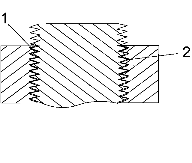
[0018] Such as figure 1 As shown, an anti-loosening thread fastening structure includes a bolt and a nut that cooperates with the bolt, the bolt is a standard metric bolt, and the thread surface at the root of the internal thread 1 of the nut is provided with a variable-angle slope 2, The remainder of the internal thread 1 is the same as a standard metric nut. The threads on the bolts and nuts are triangular threads, the profile angle is 60°, and the included angle between the variable-angle slope 2 and the bisector of the profile angle of the internal thread 1 is 31.6°.
[0019] When the nut and the bolt in this embodiment are screwed together, because the variable-angle slope 2 occupies part of the screw groove bottom space of the nut, the fit gap is eliminated. The upper thread surface of the thread is limited by the lower thread surface of the nut thread above the bolt thread, so the bolt and the nut will produce strong mutual extrusion at the beginning of cooperation, wh...
Embodiment 2
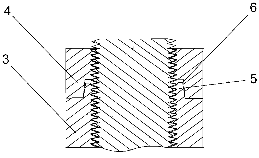
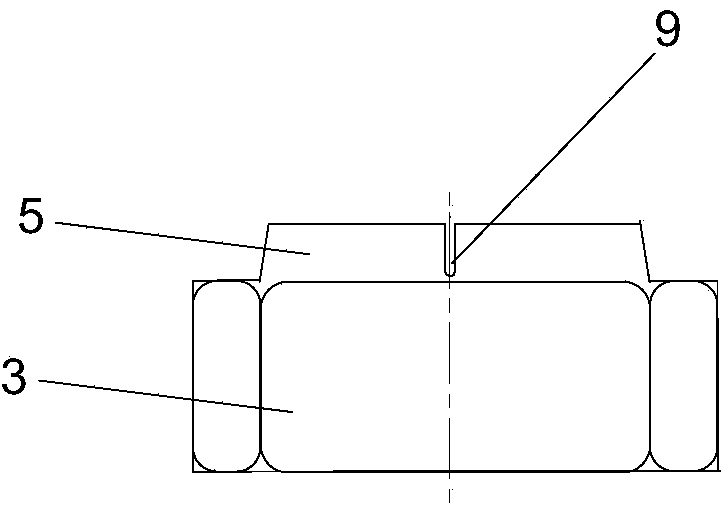
[0021] Such as figure 2 , image 3 As shown, there are two nuts, including a lock nut 3 and a lock nut 4. The lock nut 3 is mainly used to cooperate with the bolt to exert a tightening force on the fastening object, and the lock nut 4 prevents the lock nut from 3 back, thereby playing a role in strengthening fastening. On the lock nut 3, an axially protruding lock ring 5 is integrally formed in the center of the end face opposite to the lock nut 4. The outer profile of the lock ring 5 gradually narrows from the root to the free end. The inner wall is provided with a thread that continues to the internal thread of the locking nut 3, and the locking ring 5 is provided with three slits 9 radially penetrating the inner and outer walls of the locking ring 5, and the locking ring 5 is divided into three petals, each of which can be For a small deflection, on the locknut 4, an axially concave tightening opening 6 is provided in the center of the end face opposite to the locking nu...
Embodiment 3
[0024] Such as image 3 As shown, there are two nuts, including a lock nut 3 and a lock nut 4, the lock nut 3 is provided with an eccentric concave hole 7, and the eccentric concave hole 7 is located on the end face opposite to the lock nut 4, preventing The loose nut 4 is provided with an eccentric convex ring 8, and the eccentric convex ring 8 is located on the end face opposite to the lock nut 3. The offset distance between the axis of the lock nut 3 and the axis of the lock nut 3 is equal to the offset distance between the eccentric protruding ring 8 and the axis of the lock nut 4 . All the other are with embodiment 1.
[0025]In this embodiment, the lock nut 3 and the lock nut 4 can also form a reinforced anti-loosening thread fastening structure with the bolt 10 . After the lock nut 3 and the bolt 10 are screwed together, the lock nut 4 is superimposed on the lock nut 3. When the lock nut 3 and the lock nut 4 are close, the eccentric convex ring 8 and the eccentric con...
PUM
 Abstract
Description
Claims
Application Information
 - R&D
- Intellectual Property
- Life Sciences
- Materials
- Tech Scout
- Unparalleled Data Quality
- Higher Quality Content
- 60% Fewer Hallucinations
Browse by: Latest US Patents, China's latest patents, Technical Efficacy Thesaurus, Application Domain, Technology Topic, Popular Technical Reports.
© 2025 PatSnap. All rights reserved.Legal|Privacy policy|Modern Slavery Act Transparency Statement|Sitemap|About US| Contact US: help@patsnap.com


