Connector

A connector and contact piece technology, applied in the direction of connection, conductive connection, two-part connection device, etc., can solve the problems of poor stability and easy dislocation, and achieve the effects of stable contact, ensuring safety, and large flow area.

Active Publication Date: 2020-05-26
CHINA AVIATION OPTICAL-ELECTRICAL TECH CO LTD
View PDF6 Cites 2 Cited by
  • Summary
  • Abstract
  • Description
  • Claims
  • Application Information

AI Technical Summary

Problems solved by technology

[0007] The purpose of the present invention is to provide a connector that can solve the problem of poor

Method used


Image

  • Connector
  • Connector
  • Connector

Examples


Embodiment 1

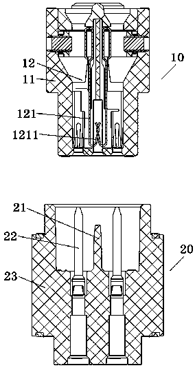
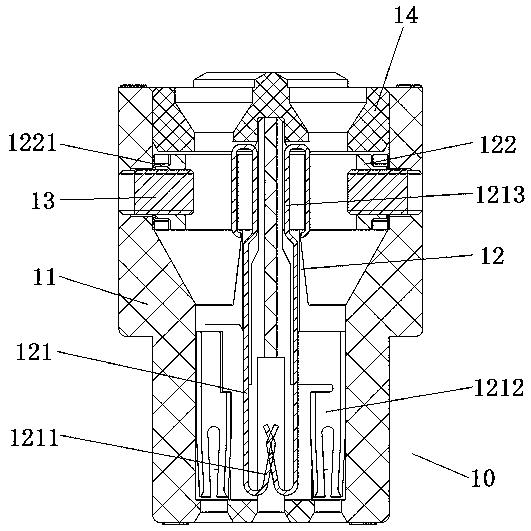
[0039] Embodiment 1 of the connector in the present invention: the connector of the present invention cooperates with the adapter connector and is used in a current transformer. The connector in the present invention is connected in the circuit of the current transformer, and the adapter connector is connected in In control equipment circuits used in conjunction with current transformers. In order to meet the technical requirement of "the current loop is not broken" when the current transformer is in use, the connector in the present invention has a self-short-circuit function (also known as an anti-open circuit function), which can The contacts in the connector are short-circuited to ensure the formation of a current loop, and the contacts in the connector are disconnected when the connector is plugged and mated with the adapter connector, so as to achieve the purpose of always keeping the current loop open.

[0040] Such as figure 1 As shown, the connector and the matching ...

Embodiment 2

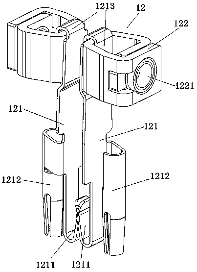
[0053] Embodiment 2 of the connector of the present invention: the difference from the above embodiments is that in this embodiment, the plug-in end of the contact piece is punched with a cantilever that can be bent outward, and the cantilever is a part of the plug-in end. The cantilever cantilever is folded back to the insertion direction to form the elastic arm structure of the contact piece, and is not limited to the solution of bending the entire extension section at the lower end of the contact piece to form the elastic arm structure.

Embodiment 3

[0054] Embodiment 3 of the connector in the present invention: the difference from the above embodiments is that in this embodiment, the plug-in end of the contact piece is first turned back to the plug-in direction, and then turned perpendicular to the plug-in direction Folding to form sockets for plugging and mating with the mating contacts in the mating connector is not limited to the solution in which an epitaxial sheet is extended perpendicular to the plugging direction on the wound contact sheet body.


PUM


Abstract

The invention relates to the technical field of electric connectors, and provides a connector. The connector comprises a connector shell, wherein paired conductive assemblies are arranged in the connector shell; the conductive assembly comprises a contact piece body, one end of the contact piece body is provided with a plug-in structure used for being matched with an adaptive plug-in piece, an elastic arm structure is folded at the end, and the other end of the contact piece body is provided with or connected with a wire pressing structure; the elastic arm structures of the two paired conductive assemblies abut against each other at a position between the two conductive assemblies, and a flaring structure is formed at the side facing the plugging direction, so that an insulator of an adaptive connector can be inserted into the flaring structure to insulate and isolate the two elastic arm structures in use. The elastic arm structures for realizing short circuit of the two conductive assemblies are integrally formed on the contact piece body, the plugging structure, the elastic arm structures and the contact piece body are relatively fixed, and the elastic arm structures can be always located at the accurate matching positions in the plugging process of the connector, so that the elastic arm structures do not move when a short circuit function is realized, and the stability of the connector during working is ensured.

Description

technical field [0001] The invention relates to the technical field of electrical connectors, in particular to a connector. Background technique [0002] In the occasion where current transformers are used, there is a requirement that the current loop in the current transformer is not disconnected, so when the operator matches the connector and the current transformer, the connector should have a self-short circuit function to increase the safety of the system. Connectors with self-short-circuit function are called self-short-circuit connectors. The difference between the self-short-circuit connector and the general connector is that it can realize automatic short-circuit and automatic release of short-circuit according to the needs, that is, after the plug and socket are separated, the short-circuit mechanism in the self-short-circuit connector works, and the short-circuit contacts are short-circuited to each other to realize the short-circuit function and Withstand voltag...

Claims


Application Information

Patent Timeline
IPC IPC(8): H01R29/00H01R13/02H01R24/00H01R4/48
CPCH01R4/4809H01R13/02H01R24/005H01R29/00
Inventor 唐盘龙赵武刚方华剑胡国闯
Owner CHINA AVIATION OPTICAL-ELECTRICAL TECH CO LTD
Why Eureka
Try Eureka