
Mounting method for temperature transmitter thermosensors of electric cooker

A technology of temperature sensors and heat-sensitive elements, which is applied to parts of thermometers, thermometers, instruments, etc., can solve the problems of increased waste of resources, fragile magnetic steel, and waste of manpower, and achieve high product reliability, stable positioning, and universal use good sex effect

Inactive Publication Date: 2009-09-23
信宜市福尔电子有限公司
View PDF0 Cites 10 Cited by
  • Summary
  • Abstract
  • Description
  • Claims
  • Application Information

AI Technical Summary

Problems solved by technology

Although the magnetic steel temperature limiter is simple in structure and cheap in price, the magnetic steel is fragile and there are hidden dangers of defective products that are difficult to find
Although it is more expensive to use the temperature sensor of the sudden jump thermostat and thermistor to control the temperature of cooking, the former improves the reliability and the pass rate, and the latter not only works reliably but also uses the microcomputer chip to realize multiple function control. These two temperature control methods require wires to lead out signals from the temperature sensor. In order to fix the lead wires, additional welding brackets must be positioned, which not only wastes manpower but also increases the waste of resources.
In addition, in order to be universal and reduce costs, the magnetic steel temperature limiter hardware is often used to make some improvements and install the thermistor temperature sensor. In this way, although the versatility is good, the burrs on both sides of the thermistor pressing sheet are easy to cut through. Insulation sleeve, resulting in more defective products

Method used


Image

  • Mounting method for temperature transmitter thermosensors of electric cooker
  • Mounting method for temperature transmitter thermosensors of electric cooker
  • Mounting method for temperature transmitter thermosensors of electric cooker

Examples


Embodiment 1

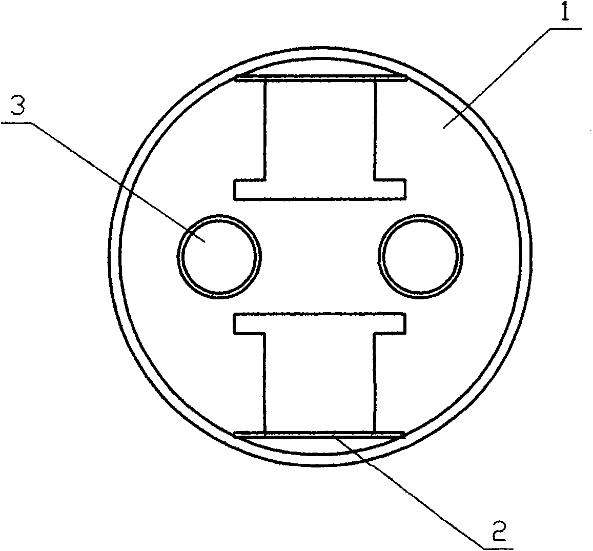
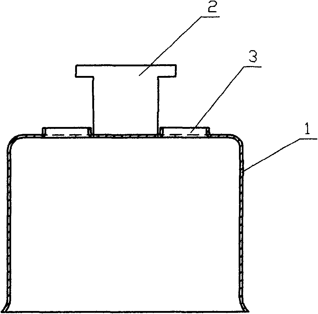
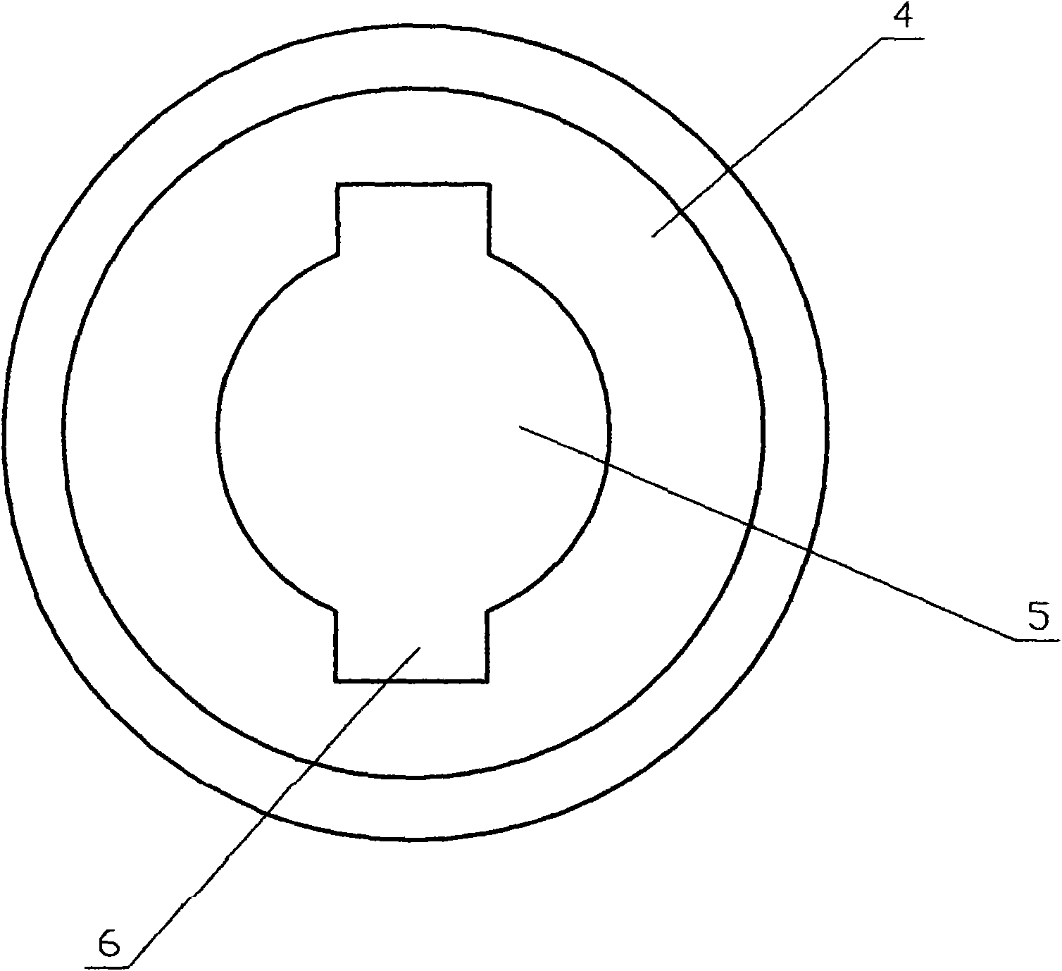
[0025] Refer to figure 1 , figure 2 , image 3 , Figure 4 , Figure 5 , Figure 6 with Figure 7 , The method for installing a thermal element of an electric rice cooker temperature sensor provided by the present invention includes the following steps:

[0026] Before the inner shell 1 of the magnetic steel temperature limiter is flushed to the bottom, two T-shaped guide feet 2 are punched symmetrically at the bottom, and then two flanging holes 3 for positioning and fixing the lead wires are punched out to obtain the inner shell 1. see figure 1 , figure 2 ;

[0027] Before the bottom of the magnetic steel temperature limiter housing 4 is flushed, a round hole 5 is punched at the bottom and the round hole has two guide grooves 6 to obtain the housing 4, see image 3 ;

[0028] Process a pressing piece 7, the pressing piece is punched with two flanging openings 8, which are U-shaped or through holes, and a groove 9 is formed between the two flanging openings 8, see Figure 4 , ...

Embodiment 2

[0033] Refer to Figure 7 , The difference from Embodiment 1 is that the temperature control element 10 is a thermostat, which is an assembly drawing of a snap-type thermostat. The snap-type thermostat is used as a temperature control switch for an electric rice cooker, and its lead 11 is inserted through The pressing piece 7 does not need a flanging hole, and its function is to press the snap-type thermostat tightly, and the insert is tightened by the insulating sleeve. The remaining hardware such as the inner shell 1, the outer shell 4, etc. are the same as those in the first embodiment. The wrapped lead wire 11 passes through the flanged hole 3 of the inner shell 1 and is fixed, so there is no need to weld another positioning piece.


PUM


Abstract

The invention relates to a mounting method for temperature sensor thermosensors of an electric cooker. The mounting method comprises the following steps: providing an inner shell (1) with a bottom punched with two T-shaped guide feet and a turnup hole for positioning and fixing extracted leads (11); providing an outer shell (4) with a bottom punched with a round hole and two guide grooves in the round hole; mounting a temperature control element (10) in a groove of tablettings (7), penetrating the leads (11) wrapped by a sleeve out of the turnup holes at the bottom of the inner shell (1) to be tightly matched with and fixed on the turnup holes; arranging the tablettings (7) between the inner shell (1) and an aluminum cover (13) to be riveted and compacted and using the tablettings (7) to compact temperature control element (10); supporting the inner shell (1) in the outer shell (4) by springs (12), penetrating the leads (11) wrapped by the sleeve out of the round hole of the outer shell (4), and penetrating the T-shaped guide feet of the inner shell (1) out of the round hole of the outer shell (4) to be bent in the guide grooves of the outer shell (4). The mounting method for the temperature sensor thermosensors of the electric cooker can reduce materials, decrease the cost, improve the qualified rate and ensure the product to be more reliable in the working process.

Description

Technical field [0001] The invention relates to a method for manufacturing a temperature sensor of an electric cooker, in particular to a method for installing a thermal element of the temperature sensor of an electric cooker. Background technique [0002] At present, in the rice cooking temperature control of the rice cooker, in addition to using the traditional magnetic steel temperature limiter to limit the temperature, there are also temperature sensors that use snap-type thermostats and thermistors as the thermal elements for cooking. temperature control. Although the magnetic steel temperature limiter has a simple structure and low price, the magnetic steel is fragile, and it is difficult to find the hidden danger of defective products. Although the temperature sensor using sudden jump thermostat and thermistor is more expensive for cooking temperature control, the former improves the reliability and pass rate, and the latter not only works reliably, but also realizes a var...

Claims


Application Information

Patent Timeline
IPC IPC(8): A47J27/00G01K1/14
Inventor 梁其章梁祖成
Owner 信宜市福尔电子有限公司
Learn More