Movable limiting type clothes drying machine

A technology for clothes drying machines and drying rods, which is applied to clothes lines, washing devices, textiles, and paper making, etc., can solve the problem that the upper travel limit detection switch is not accurate enough, affects the normal use of the electric clothes drying machine, and the rise cannot be truly in place. and other problems to achieve the effect of solving unstable work performance, tight occlusion, and uniform force.

Inactive Publication Date: 2017-08-11
曾琼
View PDF0 Cites 6 Cited by
  • Summary
  • Abstract
  • Description
  • Claims
  • Application Information

AI Technical Summary

Problems solved by technology

[0004] The above-mentioned patent is not safe and reliable enough in practical application, that is to say, the performance is not stable enough. In order to solve the problems existing in the above-mentioned patent, the technical solution of the above-mentioned patent is improved
[0005] At present, the winding mechanism of an electric clothes dryer is generally composed of a wire reel and a transmission device. When the wire reel rolls and unwinds the wire rope, it must ensure that the wire rope tightly bites the thread of the wire reel, and no misalignment will occur, otherwise the wire rope will be worn and broken. Knotted, affecting the normal use of the electric clothes dryer
[0006] The existing electric clothes dryer also has the following defects: when the wire rope is retracted and unwound by the reel, travel limit detection is required. There are two existing methods, one is to set the upper and lower travel limit detection switches at the end of the clothes dryer On the mounti

Method used


Image

  • Movable limiting type clothes drying machine
  • Movable limiting type clothes drying machine
  • Movable limiting type clothes drying machine

Examples


Embodiment Construction

[0031] In order to enable those skilled in the art to better understand the technical solution of the present invention, the present invention will be described in further detail below in conjunction with the accompanying drawings and specific embodiments. And the features in the embodiments can be combined with each other.

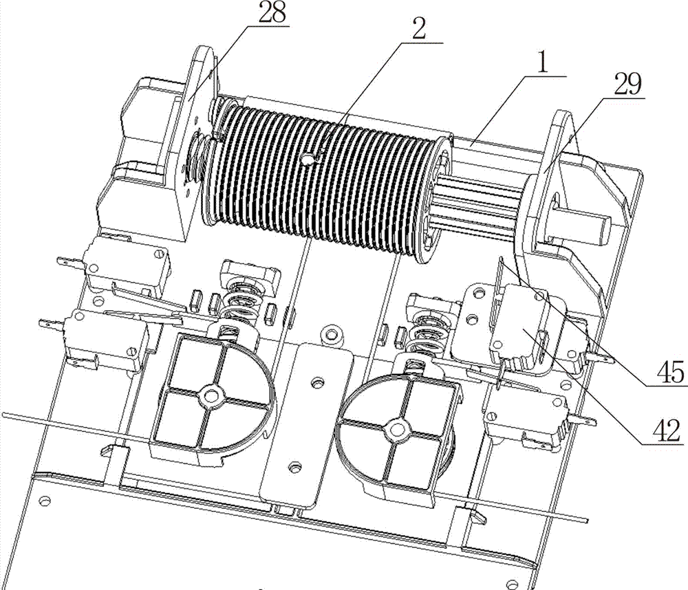
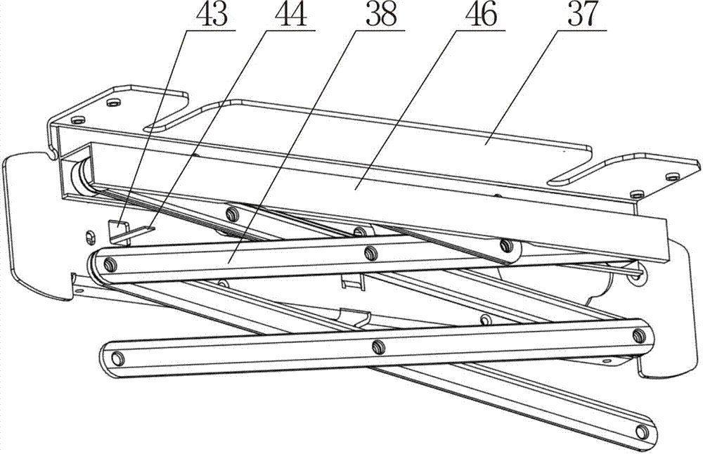
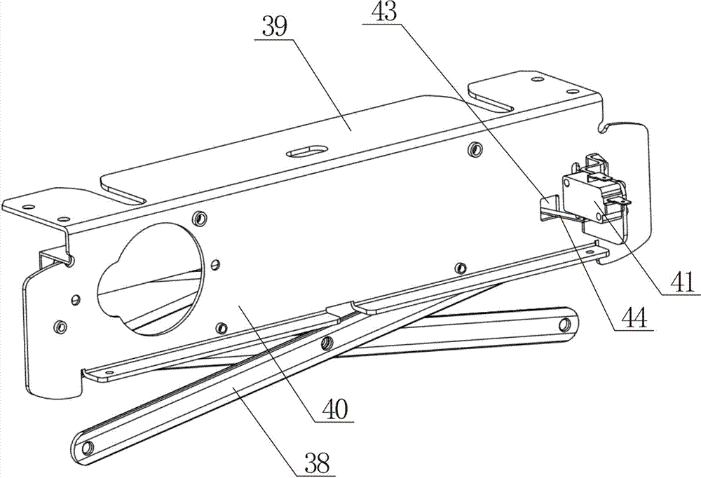
[0032] Such as figure 1 , 2 . As shown in 3, the mobile limit type clothes dryer includes a transmission support plate 1, a wire reel 2, an L-shaped mounting plate 37 and a scissor type telescopic frame 38, and the wire reel 2 is installed on the installation frame 28 of the transmission support plate 1 And on the mounting frame 29, the L-shaped mounting plate 37 includes a top panel 39 and a side panel 40, the upper end of the scissors-type telescopic frame 38 is installed in the slide rail 46 on the side panel 40, and the lower end of the scissors-type telescopic frame 38 is installed The clothes rail, the hanging rope 12 on the reel 2 drives the clot...


PUM


Abstract

The invention discloses a mobile position-limiting clothes dryer, which comprises a transmission support plate, a wire reel, an L-shaped mounting plate and a scissor-type telescopic frame. The L-shaped mounting plate includes a top panel and a side panel, and a scissor-type telescopic frame. The upper end of the upper end is installed in the slide rail on the side panel, and also includes an upper and lower limit travel switch, and the upper and lower limit travel switch includes an up limit travel switch and a down limit travel switch, and the side panel in the L-shaped mounting plate There is a hole on the top, the switch shrapnel in the upward limit travel switch passes through the hole, the clothes rail goes up, and when the scissor-type telescopic frame shrinks, the scissors in the scissor-type telescopic frame touch the switch of the upward limit travel switch The shrapnel triggers the upward limit travel switch to control the driving motor of the wire reel to stop running, thereby improving the stability and reliability of the wire reel mechanism.

Description

technical field [0001] The invention relates to a clothes dryer, in particular to an electric clothes dryer. Background technique [0002] In recent years, with the development of science and technology and the improvement of people's living standards, electric clothes dryers have been widely promoted. Electric clothes dryers can control the automatic decline and rise of the clothes rail, which facilitates people's daily clothes drying. However, if the electric clothes dryer encounters an obstacle when controlling the automatic descent of the clothes drying pole, the wire rope is slack, and the winding system still continues to unwind, which will cause the wire rope to become knotted and affect the normal use of the clothes dryer; When the machine controls the automatic rising of the clothes drying pole, if you encounter problems such as overweight or being stuck, if you continue to control the operation, the internal motor transmission device, wire rope and other components...

Claims


Application Information

Patent Timeline
IPC IPC(8): D06F57/12D06F53/00
CPCD06F57/12D06F53/045
Inventor 曾琼
Owner 曾琼
Why Eureka
Try Eureka