Intelligent glasses with blinking detection function and implementation method thereof

A technology of smart glasses and implementation methods, applied in glasses/goggles, diagnostic records/measurement, medical science, etc., can solve the problems of reduced accuracy, complex sensors, and difficulty in integrating glasses, etc., to achieve low complexity and accurate judgment high degree of effect

Inactive Publication Date: 2014-11-12
GUANGZHOU HKUST FOK YING TUNG RES INST
7 Cites 39 Cited by

AI-Extracted Technical Summary

Problems solved by technology

However, the sensors that monitor EEG signals are too complex to integrate on glasses,...

Abstract

The invention discloses a pair of intelligent glasses with the blinking detection function and an implementation method of the intelligent glasses. The intelligent glasses comprise a glasses frame, a glasses bridge, eyeglasses, nose supports and glasses legs, wherein the nose supports and the glasses legs are respectively provided with a myoelectricity sensor; the glasses bridge is provided with a vibration reminder, and each glasses leg is provided with a myoelectricity signal processing device and a camera. The implementation method includes the following steps that 1, an eye change myoelectricity signal is collected through the myoelectricity sensors; 2, the collected myoelectricity signal is sent to a signal processing circuit for processing, and myoelectricity signal features are obtained; 3, the obtained myoelectricity signal features are compared with preset myoelectricity signal features, one-time blinking is judged if the obtained myoelectricity signal features are coincident with the preset myoelectricity signal features, and next judgment is carried if the obtained myoelectricity signal features are not coincident with the preset myoelectricity signal features; 4, the number of blinking times within a unit time is obtained, and the blinking frequency is obtained; 5, whether a user blinks abnormally or not is judged according to the blinking frequency, and the vibration reminder vibrates for reminding if it is judged that the user blinks abnormally. The intelligent glasses with the blinking detection function and the implementation method of the intelligent glasses can effectively protect the eyes in time.

Application Domain

Technology Topic

Blink detectionEye change +8

Image

  • Intelligent glasses with blinking detection function and implementation method thereof
  • Intelligent glasses with blinking detection function and implementation method thereof
  • Intelligent glasses with blinking detection function and implementation method thereof

Examples

  • Experimental program(1)

Example Embodiment

[0033] The following detailed description will be given in conjunction with the embodiments with reference to the accompanying drawings in order to give a more in-depth interpretation of the technical features and advantages of the present invention.
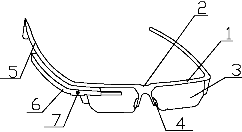
[0034] The structure diagram of the present invention is as figure 1 As shown, a smart glasses with blink detection function includes a frame 1, a bridge 2, a lens 3, a nose pad 4, and a temple 5, and an electromyographic sensor is provided on the nose pad 4 and the temple 5, respectively. The mirror bridge 2 is provided with a vibration reminder, and the mirror foot 5 is also provided with an electromyography signal processing device 6 and a camera 7.
[0035] The EMG sensor is a skin surface EMG sensor arranged on the skin surface. Generally, its circuit structure consists of four parts: pre-stage, amplifier stage, notch stage and output stage. Its characteristic is that two operational amplifiers made of the same silicon chip form a pre-stage with in-phase parallel input. The notch stage adopts Double T active network. The surface electromyography signal (sEMG) is a non-stationary weak signal generated by the motor unit action potential trains (MUAPT) generated by the motor units recruited when the muscle is excited.
[0036] Preferably, the electromyography signal processing device 6 is provided with an electromyography signal processing circuit, and the electromyography signal processing circuit is composed of a central processing unit. The central processing unit includes calculation, analysis, judgment and processing after receiving the EMG signal, and issuing reminding instructions.
[0037] Preferably, the EMG sensor on the nose pad 4 includes a three-phase interface, one phase is a ground terminal, and the other two phases are EMG differential circuits, which are respectively placed on both sides of the nose pad 4.
[0038] A method for implementing the smart glasses with blink detection function includes the following steps:
[0039] First, the method needs to preset the characteristics of the EMG signal, the steps are as follows:
[0040] Step S101. Collect the EMG signal of the eye changes through the EMG sensor. The EMG sensor includes a three-phase interface, one phase is a ground terminal, and the other two phases are EMG differential circuits, which are placed on both sides of the nose pad;
[0041] Step S102. Calculate the average value and standard deviation of the EMG signal according to the collected EMG signal; the EMG signal collected by the general EMG sensor is sent to the signal processing circuit, and the calculation unit in the central processing unit of the signal processing circuit The EMG signal processing technology calculates the average value and standard deviation of the EMG signal. It is particularly important to note that when pre-setting EMG signal characteristics, because the EMG signal characteristics of individual users are collected, so for more accurate judgment For blinking behavior, the sampling frequency of the EMG signal is much higher than the blinking frequency to accurately determine the blinking behavior, so according to different individual users, you can set your own EMG signal characteristics;
[0042] Step S103. Set the characteristics of the EMG signal caused by the blinking action as follows: first generate a signal peak value not lower than the average value + standard deviation, and then generate a signal valley value not higher than the average value-standard deviation. If the difference of the EMG signal valley value is greater than the set threshold, it is judged as a blinking action;
[0043] Step S104. Store the electromyographic signal characteristics caused by the set blinking action. Stored for the user to compare with real-time blinking in actual operation.
[0044] The method flow chart of the present invention is as figure 2 As shown, the specific steps are as follows:
[0045] Step 1. Collect the EMG signal of the eye changes through the EMG sensor. The EMG sensor includes a three-phase interface, one phase is the ground terminal, and the other two phases are EMG differential circuits, which are placed on both sides of the nose pad; the differential circuit is obtained The EMG signal is also a differential signal. After the general user puts on the glasses, the EMG sensor automatically collects the EMG signal, and after the EMG signal is collected, it is sent to the signal processing circuit for processing;
[0046] Step 2. Send the collected EMG signal to the signal processing circuit for processing to obtain the characteristics of the EMG signal. The signal processing circuit is generally composed of a central processing unit or a main chip. The EMG signal characteristics described in step 2 are real-time EMG signal characteristics, that is, the EMG signal characteristics presented by the user's eye muscle changes;
[0047] Step 3. Compare the acquired EMG signal features with the preset EMG signal features. If it is consistent with the preset EMG signal features, it will be judged as a blink, otherwise continue to the next judgment; that is, the collected EMG signal If the signal is satisfied, a signal peak value not lower than the average value + standard deviation is generated first, and then a signal valley value not higher than the average value-standard deviation is generated. The difference between the EMG signal peak value and the EMG signal valley value is greater than the set value Threshold, judged as a blinking action; if it does not meet the above requirements, continue to obtain EMG signal for re-judgment;
[0048] Step 4. Obtain the number of blinking actions per unit time to obtain the blinking frequency; because it is obviously inaccurate to determine the blinking frequency with one blinking action, it is necessary to obtain the number of multiple blinking actions to determine the blinking frequency; you can also obtain the blinking frequency within multiple units of time. Blink frequency, for example, the unit time can be set to 10 seconds, 20 seconds or longer, which can be set as required;
[0049] Step 5. Determine whether the user's blinking is abnormal according to the blinking frequency, and if it is, the vibration reminder vibrates to send out a reminder. Step 5 specifically includes:
[0050] Step S201. Acquire the blink frequency per unit time several times continuously; if the unit time is set to 10 seconds, then the blink frequency per unit time can be obtained 6 times within 1 minute; for example, the user’s blink frequency is calculated by means of a sliding window. The size of the sliding window is 1 minute, and the distance of one sliding is 10 seconds (or other settings);
[0051] Step S202. Determine whether the blinking frequency per unit time is different from the normal blinking frequency. The normal blinking frequency is preset and stored in the EMG signal processing circuit; that is, it is judged whether the blinking frequency of 6 times per unit time is different from the normal blinking frequency. Blink frequency, assuming that the normal blink frequency is 6-30 times per minute, higher or lower than both are judged to be different from the normal blink frequency;
[0052] Step S203. If the blinking frequency of several consecutive times is different from the normal blinking frequency, the vibration reminder is triggered to vibrate to remind. In order to improve the accuracy, it is generally set that the blinking frequency of several consecutive times is different from the normal blinking frequency, because in special circumstances Next, the user’s attention or other foreign objects can easily affect the blink frequency and cause misjudgment. Therefore, if the blink frequency is abnormal for several consecutive times, the vibration reminder will be activated. The vibration reminder has a built-in vibration chip or a vibration motor.
[0053] As a preferred embodiment of the present invention, the present invention can store the user's usage and use the data as one of the basis for judging diseases, such as Tourette's disease, stroke, and nervous system abnormalities.
[0054] Preferably, the method further includes turning off the vibration reminder, and turning off the vibration reminder is achieved manually or automatically. The manual mode closing includes the user closing the vibration reminder by touching or pressing the vibration reminder. The automatic mode closing includes: preset vibration time and vibration mode of the vibration reminder. For example, the user can manually turn off the vibration reminder. If the user does not manually turn off the vibration reminder, it will be automatically turned off after 10 seconds (or other set duration). The vibration time length of the reminder vibration circuit can be manually set by the user in advance; the vibration mode of the reminder vibration circuit can be manually set by the user in advance; when the vibration circuit does not stop vibrating, the user can manually turn off the vibration.
[0055] Preferably, the method further includes controlling a specific operation operation of the camera by setting a specific blinking frequency. The specific blinking frequency is setting the number of rapid blinks and the time interval between two blinks. The specific operations include turning on and off the camera and taking pictures. . For example, the specific blink frequency (such as two fast blinks, three fast blinks) is determined in advance through the settings and storage, and the specific blink frequency is combined with specific operations (such as turning on/off the smart glasses camera); when the monitoring user shows Perform a specific operation when the blink frequency has been stored. Blink twice quickly to turn on the glasses camera, blink three times quickly to turn off the camera, or blink multiple times to take a picture.
[0056] Such as image 3 Shown is a schematic diagram of the present invention for judging blinking action based on EMG signal. In the figure, the horizontal axis 11 is time (unit: second), the vertical axis 12 is the virtual value of signal strength, the solid waveform 13 is the EMG signal, and the solid circle is 14 For the real blinking behavior, the star 15 is the smart glasses to judge the blinking behavior of the user. according to image 3 The waveform of the EMG signal shown determines the real blinking behavior. Can effectively obtain the blink frequency per unit time. Therefore, the user is reminded to take eye protection measures in time, such as increasing or reducing the frequency of blinking, or doing eye exercises, so as to achieve the purpose of protecting the glasses.
[0057] In addition, the present invention can also judge the user's typical behaviors and expressions based on the electromyographic signals of the nose pads, mirror feet and other parts of the glasses, thereby judging the user's emotions based on the expressions and behaviors.
[0058] The present invention is described clearly and completely through the technical solutions in the above embodiments. It is obvious that the described embodiments are part of the embodiments of the present invention, rather than all the embodiments. Based on the embodiments of the present invention, all other embodiments obtained by those of ordinary skill in the art without creative work shall fall within the protection scope of the present invention.

PUM

no PUM

Description & Claims & Application Information

We can also present the details of the Description, Claims and Application information to help users get a comprehensive understanding of the technical details of the patent, such as background art, summary of invention, brief description of drawings, description of embodiments, and other original content. On the other hand, users can also determine the specific scope of protection of the technology through the list of claims; as well as understand the changes in the life cycle of the technology with the presentation of the patent timeline. Login to view more.

Similar technology patents

Classification and recommendation of technical efficacy words

  • Reduce complexity
  • Improve the accuracy of judgment

Identifying software execution behavior

ActiveUS20130185798A1Reduce complexityDecompilation/disassemblyMemory loss protectionSoftware executionComputer program
Owner:ACCESSDATA GRP INC

Thin client intelligent transportation system and method for use therein

InactiveUS20080114530A1Reduce complexityElimination of map integrity issueAnalogue computers for vehiclesAnalogue computers for trafficMap matchingIntelligent transportation system
Owner:PETRISOR GREGORY C +2

Non-systematic coded error correction

ActiveUS20060248434A1Facilitate detection and correctionReduce complexityStatic storageRedundant data error correctionData bitsData security
Owner:OVONYX MEMORY TECH LLC

Parking lot management system and management method

PendingCN106205185ASimple parking guidance service and reverse car search serviceImprove the accuracy of judgmentIndication of parksing free spacesVirtualizationParking space
Owner:鲍星合
Why Eureka
Try Eureka