
Stepping switch assembly and electromagnetic stepping relay

A stepping switch and relay technology, applied in electromagnetic relays, electromagnetic relay details, relays, etc., can solve problems such as temperature rise, large frictional resistance between the moving contact bracket and driving parts, and inability to meet diverse needs, and achieve Effects of temperature and noise reduction, increased service life, and reduced frictional resistance

Active Publication Date: 2014-11-12
北京ABB低压电器有限公司
View PDF5 Cites 1 Cited by
  • Summary
  • Abstract
  • Description
  • Claims
  • Application Information

AI Technical Summary

Problems solved by technology

[0003] The stepping switch of the electromagnetic relay in the prior art usually uses gears, ratchets and other components to directly drive the moving contact bracket, and the moving contact bracket is mainly supported by springs to realize reciprocating motion, resulting in frictional resistance between the moving contact bracket and the driving parts Large, so the coil needs to provide a large driving force, which is easy to cause temperature rise, which is not conducive to product performance protection
The stepping switch of the electromagnetic relay in the prior art can only control the dynamic and static contacts on both sides to cooperate or separate at the same time, so that the circuits on both sides are closed or disconnected at the same time, which cannot realize the function of two simultaneous and precise steps , can not meet the diverse needs, such as the need for one side of the circuit to be closed, the other side of the circuit to be turned on, etc.
And it is also impossible to switch between the four states of open-open, open-closed, closed-closed and closed-open.

Method used


Image

  • Stepping switch assembly and electromagnetic stepping relay
  • Stepping switch assembly and electromagnetic stepping relay
  • Stepping switch assembly and electromagnetic stepping relay

Examples


Embodiment Construction

[0052] The specific implementation manner of the present invention will be further described below in conjunction with the accompanying drawings. Wherein the same components are denoted by the same reference numerals. It should be noted that the words "front", "rear", "left", "right", "upper" and "lower" used in the following description refer to the directions in the drawings, and the words "inner" and "outer ” refer to directions towards or away from the geometric center of a particular part, respectively.

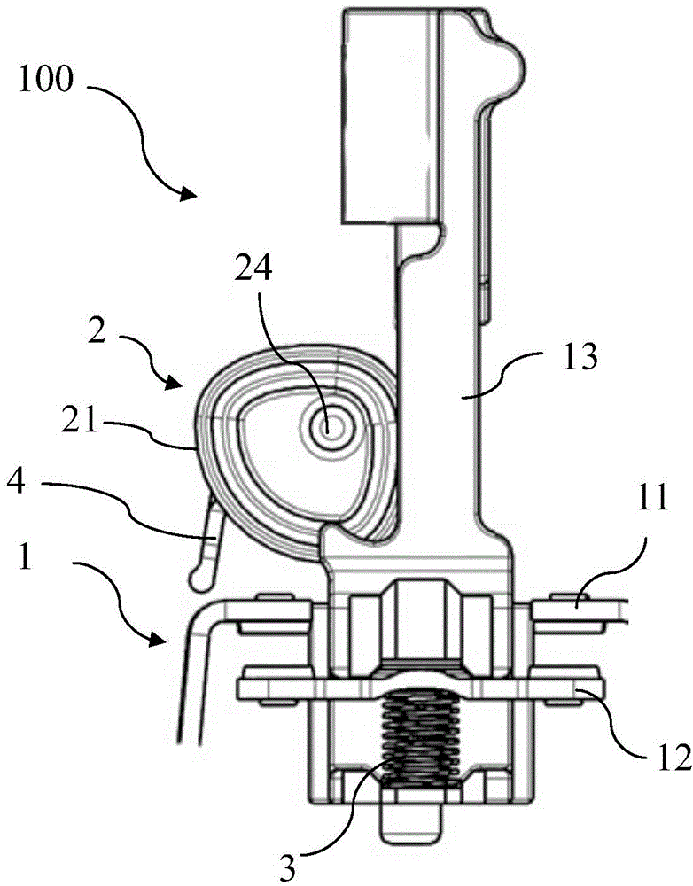
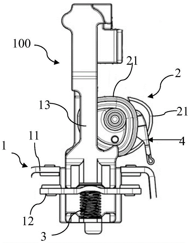
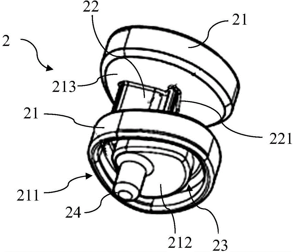
[0053] Such as Figure 1-4 As shown, a step switch assembly 100 provided by an embodiment of the present invention is used in an electromagnetic step relay.

[0054] The step switch assembly 100 includes two groups of moving and static contact assemblies 1, and each group of moving and static contact assemblies 1 includes a fixed fixed contact 11, a moving contact 12 that is slidably separated from or matched with the static contact 11, and a driving moving contact. T...


PUM


Abstract

The invention discloses a stepping switch assembly which comprises two movable and static contact assemblies. Each movable and static contact assembly comprises a static contact, a movable contact capable of being separated from or matched with the static contact in a sliding mode, and a movable contact support driving the movable contact to move. The stepping switch assembly further comprises a driving cam assembly used for driving the movable contact supports to slide. The driving cam assembly comprises two cams and a ratchet located between the two cams, and the two cams rotate with a rotating shaft as the axis. The side face of each cam is provided with a cam sliding groove, the two movable contact supports are in sliding contact with the cam sliding grooves in the two cams respectively, and the movable contact supports can slide relative to the cam sliding grooves. The invention further discloses an electromagnetic stepping relay. Friction force is small, and the function of simultaneous precise stepping of two circuits can be achieved.

Description

technical field [0001] The invention relates to the technical field of relays, in particular to a step switch assembly used in an electromagnetic step relay and an electromagnetic step relay with the step switch assembly. Background technique [0002] Electromagnetic relays are generally composed of iron cores, coils, armatures, step switches, moving contacts, static contacts and other components. The moving and static contacts on both sides are controlled by the step switch to cooperate or separate, so as to control the closing or breaking of the circuit. [0003] The stepping switch of the electromagnetic relay in the prior art usually uses gears, ratchets and other components to directly drive the moving contact bracket, and the moving contact bracket is mainly supported by springs to realize reciprocating motion, resulting in frictional resistance between the moving contact bracket and the driving parts Large, so the coil needs to provide a large driving force, which is...

Claims


Application Information

Patent Timeline
IPC IPC(8): H01H50/64H01H50/54
Inventor 吕亚楠王嘉庆
Owner 北京ABB低压电器有限公司
Learn More