Generator with simultaneous cooling of multiple components

A generator, multi-component technology, used in cooling/ventilation devices, electrical components, electromechanical devices, etc., can solve the problems of decreased insulation of motor components, increased temperature of mufflers, and inability to cool, so as to improve cooling effect and reduce manufacturing. cost, the effect of improving heat dissipation efficiency

Active Publication Date: 2017-11-21
重庆乾威科技有限公司
View PDF5 Cites 0 Cited by
  • Summary
  • Abstract
  • Description
  • Claims
  • Application Information

AI Technical Summary

Problems solved by technology

Existing generator comprises following structure: engine, motor assembly (motor assembly includes rotor and stator), cooling fan, inverter, muffler, frame and oil tank; Generator can produce a large amount of heat in the course of work, and these heat It mainly comes from the engine, motor components and inverter. The high-temperature exhaust gas generated by the engine will also cause the temperature of the muffler to rise. This heat will seriously affect the performance of the generator. For example, if the temperature is too high, the insulation of the motor components will decrease. , and even cause the generator to burn out; if the temperature is too high, the performance of the inverter will decrease; although the engine itself has a cooling system, its local temperature will also be too high, resulting in a decrease in the performance of the engine. If the temperature is too high, it will also affect the motor components. For the temperature problem of the generator, there are currently many designs. Although it can play a role in the heat dissipation of the generator, it cannot simultaneously control the inverter, the engine and the motor components. Cooling, if all the above-mentioned components are cooled, but the design structure of the cooling air duct is extremely complicated, which will increase the difficulty of manufacturing the generator itself, thereby increasing the manufacturing cost of the generator

Method used


Image

  • Generator with simultaneous cooling of multiple components
  • Generator with simultaneous cooling of multiple components
  • Generator with simultaneous cooling of multiple components

Examples


Embodiment Construction

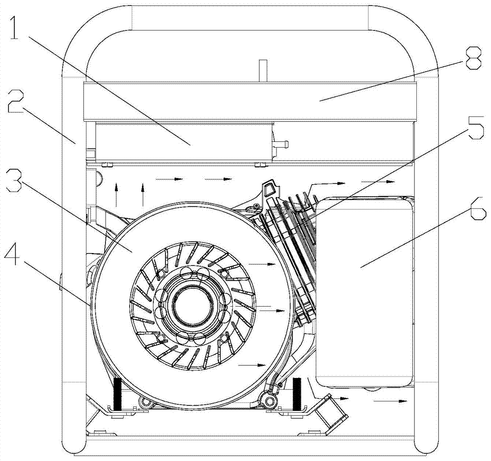
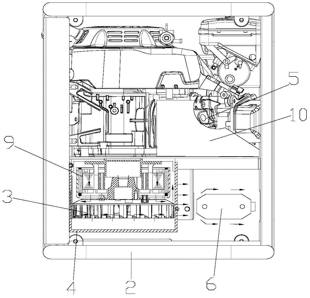
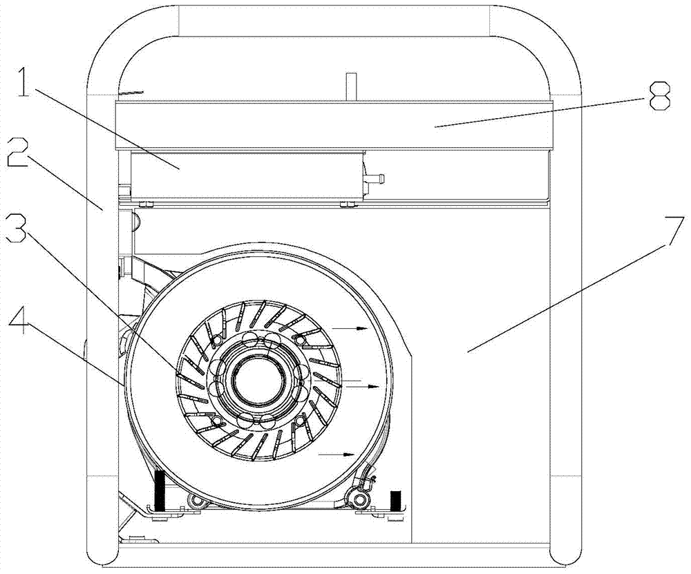
[0017] figure 1 It is the front view of the present invention, figure 2 It is a top view of the present invention, as shown in the figure, a multi-component simultaneous cooling generator provided by the present invention includes at least an engine 5, a motor assembly 9 connected to the engine 5, and a mounting bracket for installing the engine 5 and the motor assembly 9 The frame 2 is characterized in that it also includes a centrifugal fan 3, an inverter 1 and a muffler 6, the centrifugal fan 3 is arranged at the rear end of the motor assembly 9 and the motor assembly 9 is located between the fan 3 and the engine 5 And the air is formed to flow from the engine 5 to the centrifugal fan 3 and the double air-intake heat dissipation channel that flows in from the rear end of the centrifugal fan 3. The fan 3 is connected to the engine 5 in transmission, and the muffler 6 and the inverter 1 are provided. On the air outlet side of the centrifugal fan 3 and the muffler 6 is locat...


PUM


Abstract

The invention provides a multi-component simultaneously cooled generator, which at least includes an engine, a motor assembly connected to the engine transmission, and a frame for installing the engine and the motor assembly, and is characterized in that it also includes a centrifugal fan and an inverter And the muffler, the centrifugal fan is arranged at one end of the motor assembly and the motor assembly is located between the fan and the engine to form a double air intake heat dissipation passage where the air flows from the engine to the centrifugal fan and from the outside of the centrifugal fan, The fan is connected to the engine drive, the muffler and inverter are arranged on the air outlet side of the centrifugal fan and the muffler is located at the air outlet of the heat dissipation channel; cooling, and has a simple structure and is easy to manufacture, reducing the manufacturing difficulty and cost of the generator.

Description

technical field [0001] The invention relates to a generator, in particular to a generator with simultaneous cooling of multiple components. Background technique [0002] Generators are extremely important power supply equipment in modern life, and are widely used in backup power supply, field operations and other fields. Existing generator comprises following structure: engine, motor assembly (motor assembly includes rotor and stator), cooling fan, inverter, muffler, frame and oil tank; Generator can produce a large amount of heat in the course of work, and these heat It mainly comes from the engine, motor components and inverter. The high-temperature exhaust gas generated by the engine will also cause the temperature of the muffler to rise. This heat will seriously affect the performance of the generator. For example, if the temperature is too high, the insulation of the motor components will decrease. , and even cause the generator to burn out; if the temperature is too h...

Claims


Application Information

Patent Timeline
Patent Type & Authority Patents(China)
IPC IPC(8): H02K9/06
Inventor 庞志强
Owner 重庆乾威科技有限公司
Why Eureka
Try Eureka