Vane displacement error detection device of multi-vane collimator

A multi-leaf collimator, displacement error technology, applied in the directions of X-ray/γ-ray/particle irradiation therapy, etc., can solve the problem of inability to know the error value, achieve convenient operation, solve the problem that the hysteresis value cannot be accurately measured, and the structure simple effect

Inactive Publication Date: 2014-11-19
SHANDONG JIAOTONG UNIV
View PDF4 Cites 25 Cited by
  • Summary
  • Abstract
  • Description
  • Claims
  • Application Information

AI Technical Summary

Problems solved by technology

If the actual displacement of the blade cannot be measured, it is impossible to know the theoretical displacement output by the control system for comparison, so that the error value cannot be known

Method used


Image

  • Vane displacement error detection device of multi-vane collimator
  • Vane displacement error detection device of multi-vane collimator
  • Vane displacement error detection device of multi-vane collimator

Examples


Embodiment Construction

[0014] Attached below figure 1 , attached figure 2 , attached image 3 The present invention will be further described.

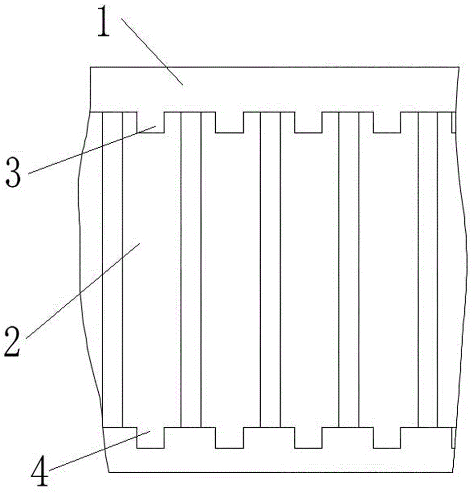
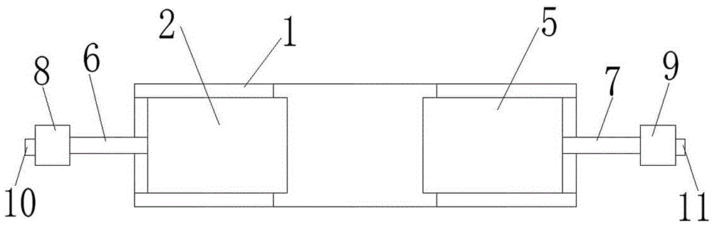
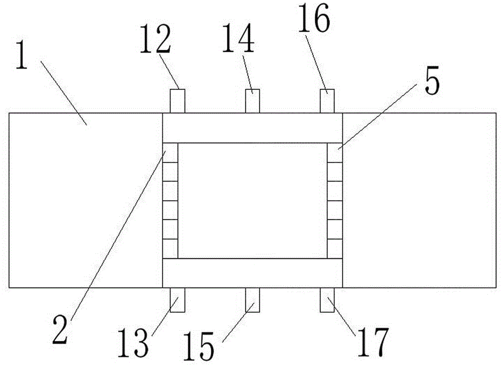
[0015] The multi-leaf collimator blade displacement error detection device includes a housing 1, a number of left blades 2 and right blades 5 that are slidably installed on the left side and right side of the housing 1 through a sliding device, and are respectively screwed on each left side. Lead screw I 6 and lead screw II 7 on blade 2 and right blade 5, motor I 8 and motor II 9 fixed on the left and right sides of housing 1, the heads of lead screw I 6 and lead screw II 7 are respectively It is connected to the output shafts of motor I 8 and motor II 9, the encoder I 10 and encoder II 11 are respectively connected to the tail ends of the output shafts of motor I 8 and motor II 9, and the infrared laser in the middle of the rear end of the housing 1 The transmitter II 14 of the sensor, the infrared laser sensor receiver II 15 is installed in the middle...


PUM


Abstract

The invention relates to a vane displacement error detection device of a multi-vane collimator. The vane displacement error detection device of the multi-vane collimator comprises a shell, a plurality of left vanes and right vanes, a lead screw I, a lead screw II, a motor I and a motor II, wherein the left vanes are installed at the left end inside the shell in a sliding mode through a sliding device, the right vanes are installed at the right end inside the shell in a sliding mode through a sliding device, the lead screw I is screwed on the left vanes, the lead screw II is screwed on the right vanes, and the motor I and the motor II are fixed to the left side and the right side of the shell respectively. Encoding signals of an encoder I and an encoder II are read and compared with the interval between an infrared laser sensor emitting end I or an infrared laser sensor emitting end III and an infrared laser sensor emitting end II, so that the differential value between the actual movement displacement amount of the vanes and the theoretical displacement amount output by a control system is obtained, and the vane displacement error detection device of the multi-vane collimator is simple in structure and convenient to operate. The practically obtained differential value is used for compensation accurately and reliably, and the problems that as the lead screws are abraded due to long-time operation, the return difference is too large and the return difference value can not be accurately measured are solved.

Description

technical field [0001] The invention relates to the technical field of medical equipment, in particular to a device for detecting blade displacement errors of a multi-leaf collimator. Background technique [0002] The multi-leaf collimator is an advanced stereotactic radiosurgery medical device, which can cooperate with a linear accelerator or a cobalt-60 machine to perform conformal intensity-modulated treatment of tumors, so as to improve the gain ratio of radiotherapy (that is, to maximize the intensity of the radiation The purpose is to concentrate the dose into the lesion, kill tumor cells, and make the surrounding normal tissues and organs receive less or avoid unnecessary irradiation). It is one of the main devices for tumor treatment today. It replaces the traditional lead baffles with several pairs of high-density tungsten alloy blades arranged in opposite directions in A and B groups to shield the rays, drives the blades and blade groups with corresponding logarit...

Claims


Application Information

Patent Timeline
Patent Type & Authority Applications(China)
IPC IPC(8): A61N5/10
Inventor 刘文江饶中洋李兴成
Owner SHANDONG JIAOTONG UNIV
Why Eureka
Try Eureka