Top-insertion type short-cantilever stator-rotor stirring device

A technology of stirring device and stator and rotor, which is applied in the directions of mixer accessories, dissolving, mixer, etc., can solve the requirement of low clearance between the stator and rotor of the higher speed of the difficult rotor, the poor working conditions of the bearing of the long cantilever stirring shaft, and it is difficult to achieve better performance. High homogeneous material mixing and other problems to achieve the effect of improving mixing effect, improving reliability and small gap

Inactive Publication Date: 2014-11-19
LIUZHOU HUT CHEM MACHINERY
View PDF4 Cites 2 Cited by
  • Summary
  • Abstract
  • Description
  • Claims
  • Application Information

AI Technical Summary

Problems solved by technology

The main disadvantages of this technology are: due to the needs of different production processes of customers, the height of the materials input each time is uncertain (the material level is high if more material is fed, and the material level is low if less material is fed), and the height of the material level fluctuates during stirring. The agitators such as the dispersing and emulsifying devices of the stator-rotor structure need to be immersed in the material. In order to meet the effective stirring at the lowest material level, the agitator needs a longer cantilever shaft, so the cantilever stiffness is low (the cantilever refers to the outlet at the fixed end. Rotary shaft between the position to the stator and rotor installation)
At the same time, due to the elastic deformation of the stirring shaft and the clearance of the bearing, it takes a higher price to achieve better transmission accuracy and a small clearance between the stator and rotor, and with the lengthening of the cantilever, interference between the stator and rotor with a small clearance is likely to occur , and the working condition of the bearing of the long cantilever stirring shaft is even worse, which can easily cause bearing damage
This kind of structure is difficult to achieve higher rotational speed of the rotor and low clearance requirements between the stator and rotor, and it is correspondingly difficult to achieve material mixing with higher homogeneity requirements

Method used


Image

  • Top-insertion type short-cantilever stator-rotor stirring device
  • Top-insertion type short-cantilever stator-rotor stirring device
  • Top-insertion type short-cantilever stator-rotor stirring device

Examples


Embodiment 1

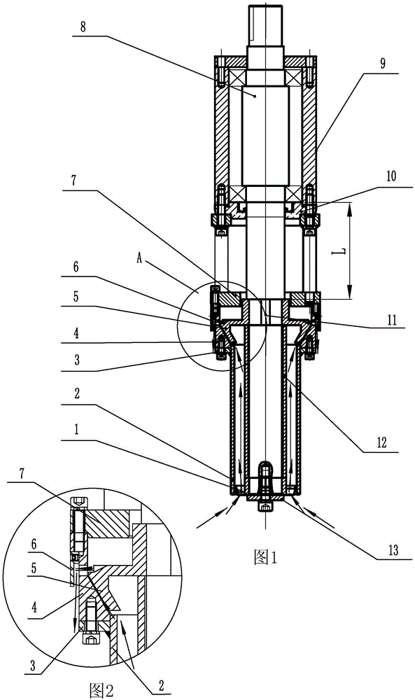
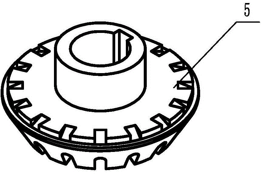
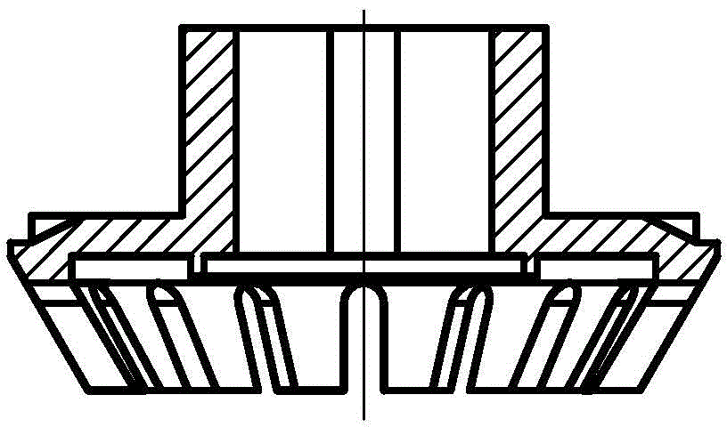
[0031] Embodiment 1: A top-inserted short cantilever stator-rotor stirring device, including a rotating shaft 8, a bearing seat 9, a bearing gland 10, an emulsification support 7, a rotor 5, a stator 4, a sleeve 2 and an inducer 1, the The inducer 1 is composed of a mounting sleeve 101 and 3 blades 102 evenly distributed on the mounting sleeve, the blades are obliquely connected to the mounting sleeve, and the inclination angle β of the blades is 20°. The bearing seat is connected with the emulsification support, the rotating shaft 8 passes through the bearing seat 9 and the emulsification support 7 and is installed in the bearing seat through a bearing, the rotor 5 is installed on the rotating shaft, and the stator 4 Located on the outside of the rotor and connected to the lower end of the emulsification bracket 7, the upper end of the sleeve 2 is fixed with a connecting plate 3, the sleeve 2 is set outside the rotating shaft 8 below the stator and connected to the bottom end ...


PUM


Abstract

The invention relates to a top-insertion type short-cantilever stator-rotor stirring device comprising a rotation shaft, a bearing seat, a bearing gland, an emulsification support, a rotor, a stator, a sleeve, and an inducer. The bearing seat is connected with the emulsification support. The rotation shaft penetrates through the bearing seat and the emulsification support, and is arranged in the bearing seat through a bearing. The rotor is arranged on the rotation shaft. The stator is positioned on the outer side of the rotor and is connected with the lower end of the emulsification support. A connection plate is arranged on the upper end of the sleeve. The sleeve is sleeved on the outer side of the rotation shaft below the stator, and is connected with the bottom end of the stator through the connection plate. The inducer is arranged on the rotation shaft, and is positioned in the sleeve. The bearing gland penetrates through the rotation shaft, and is arranged between the bearing seat and the emulsification support. According to the invention, cantilever length is greatly shortened, system stiffness is improved, and resonance frequencies of various stages are improved, such that higher rotation speed and lower space between the stator and the rotor are realized. High-quality and high-efficiency mixing of the materials is realized, and equipment reliability can be improved.

Description

technical field [0001] The invention relates to a stirring device used in mixing and stirring equipment, in particular to a top-inserted short cantilever stator-rotor stirring device. Background technique [0002] In the production of chemical industry, electronic paste, paint, adhesive, cosmetics, grease, pharmaceutical, food and many other industries, in the process of mixing materials, especially the agitator of the stator and rotor dispersion and emulsification device, most of them use the top plug-in type , and this form is the most widely used. The main disadvantages of this technology are: due to the needs of different production processes of customers, the height of the materials input each time is uncertain (the material level is high if more material is fed, and the material level is low if less material is fed), and the height of the material level fluctuates during stirring. The agitators such as the dispersing and emulsifying devices of the stator-rotor structu...

Claims


Application Information

Patent Timeline
Patent Type & Authority Applications(China)
IPC IPC(8): B01F15/00
Inventor 李行可吴真才黄学通韦初登李芸
Owner LIUZHOU HUT CHEM MACHINERY
Why Eureka
Try Eureka