Method for rolling conical barrel through plate rolling machine

A technology of plate rolling machine and cone, which is applied in the field of cone rolling, can solve the problems of large roundness tolerance, low work efficiency, long-term occupancy of cranes, etc., and achieve the goal of ensuring forming accuracy, reducing occupation time, and reducing processing costs Effect

Inactive Publication Date: 2014-11-19
CHINA NAT OFFSHORE OIL CORP +1
View PDF9 Cites 3 Cited by
  • Summary
  • Abstract
  • Description
  • Claims
  • Application Information

AI Technical Summary

Problems solved by technology

[0002] At present, the production of wind turbine towers requires a special four-roller plate rolling machine, which is expensive
In the case of the existing three-roll plate rolling machine, it is very difficult to roll the fan tower. The concentricity of the big and small openings of the cylinder and the amount of misalignment are relatively large
Due to the thin wall thickness, a crane is required to lift one end during the rolling process. The crane is occupied for a long time, and due to its own weight, the roundness tolerance after rolling is relatively large, which increases the difficulty of circle calibration.

Method used


Image

  • Method for rolling conical barrel through plate rolling machine
  • Method for rolling conical barrel through plate rolling machine
  • Method for rolling conical barrel through plate rolling machine

Examples


Embodiment Construction

[0016] In order to further understand the content, features and effects of the present invention, the following embodiments are given as examples, and detailed descriptions are as follows with accompanying drawings:

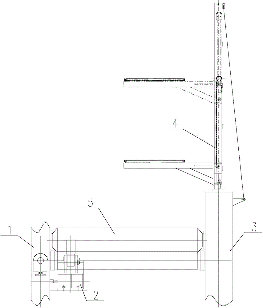
[0017] See Figure 1 ~ Figure 6 , A method of using a plate rolling machine to roll a cone. The two ends of the plate rolling machine are an overturning frame 1 and a fixed frame 3, respectively, and a cone rolling tool 2 is installed inside the overturning frame 1.

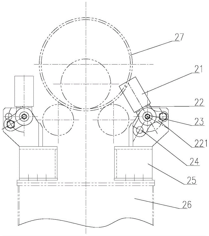
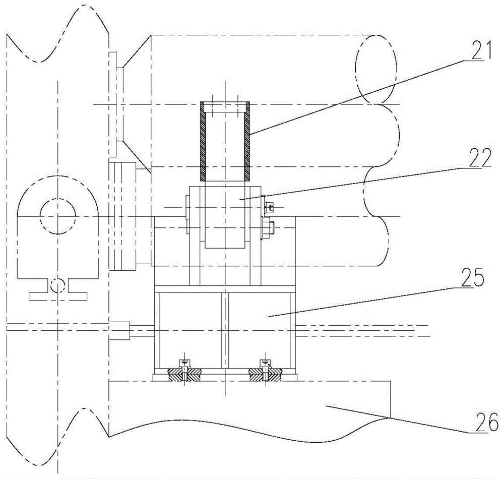
[0018] The above-mentioned cone rolling tool 2 includes a bracket 26 on which two sets of friction limit devices are provided. The structures of the two sets of friction limit devices are arranged axisymmetrically, and the axis of symmetry passes through the upper roller 5 of the bending machine. The vertical line at the center of the section; each set of friction limit devices includes a support 25 fixed to the bracket 26, a pin 23, a hinge shaft 22 and a roller sleeve 21; the upper part of the hinge sh...


PUM


Abstract

The invention discloses a method for rolling a conical barrel through a plate rolling machine. A cone rolling tool is arranged on the inner side of a turnover rack or the inner side of a fixed rack, and comprises a support, two sets of friction limiting devices are arranged on the support, and the structures of the two friction limiting devices are arranged in an axial symmetry mode. Each friction limiting device comprises a supporting seat fixedly connected with the support, a pin shaft, a hinge supporting shaft and a rolling sleeve. Supporting shafts are arranged on the upper portions of the hinge supporting shafts, locating pull arms are arranged on the lower portions of the hinge supporting shafts, and mounting holes are formed in the middles of the hinge supporting shafts. The locating pull arms are fixedly connected with the supporting seats through pins, the hinge supporting shafts are rotatably connected to the pin shafts, the two ends of each pin shaft are respectively and fixedly arranged on the corresponding supporting seat, and the rolling sleeves are fixed to the supporting shafts. When a workpiece is rolled on the plate rolling machine, the outer circle faces of the rolling sleeves are close to the small end face of the rolled conical barrel. The method has the advantages that the operation is easy and convenient, work efficiency is high, and the precision for rolling the conical barrel is high. The method is especially suitable for rolling the large-diameter thin-walled conical barrel with the conical angle larger than 15 degrees on the plate rolling machine.

Description

Technical field [0001] The invention relates to a method for rolling a cone, in particular to a method for rolling a cone using a plate rolling machine. Background technique [0002] At present, the production of wind turbine towers requires a dedicated four-roller plate bending machine, which is expensive. In the case of the existing three-roller plate rolling machine, the winding of the fan tower is very difficult. The operator needs to adjust the angle of the upper roller and master the downward pressure of the upper roller, and the work efficiency is low. The concentricity and the amount of wrong side of the tube and the mouth are large. Due to the thin wall thickness, a crane needs to be lifted during the rolling process. The crane is occupied for a long time, and due to its own weight, the roundness tolerance after rolling is relatively large, which increases the difficulty of rounding. Summary of the invention [0003] In order to solve the technical problems existing in ...

Claims


Application Information

Patent Timeline
Patent Type & Authority Applications(China)
IPC IPC(8): B21D5/14B21D51/10
Inventor 郭景红张德全徐作军孙悦刘江歌李惠珍姜竹堂杨忠祥刘光春王妍赵秀宁
Owner CHINA NAT OFFSHORE OIL CORP
Why Eureka
Try Eureka