A rolling machine

A plate rolling machine and reel technology, which is applied in the processing field, can solve the problems of low work efficiency, slow plate curling, and high cost, and achieve the effects of high work efficiency, material saving, and simple structure

Inactive Publication Date: 2018-02-06
TENGXIAN SHUNZHOU SHIPBUILDING CO LTD
View PDF5 Cites 0 Cited by
  • Summary
  • Abstract
  • Description
  • Claims
  • Application Information

AI Technical Summary

Problems solved by technology

[0002] The traditional plate curling structure is usually more complicated, the cost is higher, and the plate curling is slow, and the work efficiency is low

Method used


Image

  • A rolling machine

Examples


Embodiment Construction

[0011] Embodiments of the present invention will now be described with reference to the drawings, in which like reference numerals represent like elements.

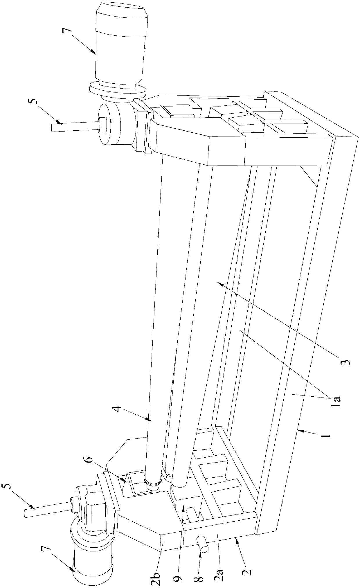
[0012] Please refer to figure 1 , the plate rolling machine includes a base 1 arranged along the X-axis, and a vertical mounting frame 2 arranged along the Z-axis is respectively provided at both ends of the base 1, and the two vertical mounting frames 2 are Openwork structure. Two lower reels 3 and an upper reel 4 are installed between the two vertical mounting frames 2, the upper reel 6 and the lower reel 3 are conical drums, and the upper reel 4 The thin end of each lower reel 3 corresponds to the thin end, and the thick end of the upper reel 4 corresponds to the thick end of each lower reel 3 . Each of the vertical mounting frames 2 is provided with a lifting screw 5 arranged along the Z axis, and a first mounting base 6 is fixed on the lower end of the lifting screw 5 . The thin end and the thick end of the upper ...


PUM


Abstract

The invention discloses a plate rolling machine which comprises a base. Two vertical mounting racks are respectively arranged at both ends of the base; two lower rolling barrels and an upper rolling barrel are mounted between the two vertical mounting racks; the upper rolling barrel and the lower rolling barrels are all conical barrels; a lifting screw rod is arranged on each vertical mounting rack; a first mounting base is fixedly arranged at the lower end of each lifting screw rod; both the thin end and the thick end of the upper rolling barrel are respectively mounted on the corresponding first mounting base; a motor is mounted on each vertical mounting rack; each motor is in linkage with the corresponding lifting screw rod by a worm gear and worm structure; two horizontal screw rods are mounted on each vertical mounting rack; a second mounting base with a nut structure is mounted on each horizontal screw rod; the nut structure of each second mounting base is matched with the corresponding horizontal screw rod; the thin ends and the thick ends of two lower rolling barrels are all respectively mounted on the corresponding second mounting bases. The plate rolling machine disclosed by the invention is simple in structure, stable in structure, high in strength and convenient to use, saves materials, and can fulfill the aim of rapidly rolling plates.

Description

technical field [0001] The invention relates to the field of processing technology, in particular to a plate rolling machine. Background technique [0002] The traditional plate curling structure is usually more complicated, the cost is higher, and the plate curling is slow, and the work efficiency is low. Contents of the invention [0003] The object of the present invention is to provide a plate rolling machine with simple structure, stable structure, good strength, high working efficiency, material saving, convenient use, and rapid plate rolling. [0004] In order to achieve the above object, the present invention provides a plate rolling machine, which includes a base set along the X axis, and a vertical mounting frame set along the Z axis is respectively provided at both ends of the base, and the two vertical mounting frames The racks are all hollowed out, and two lower reels and one upper reel are installed between the two vertical mounting racks. Both the upper ree...

Claims


Application Information

Patent Timeline
Patent Type & Authority Patents(China)
IPC IPC(8): B21D5/14
CPCB21D5/14
Inventor 莫胜新
Owner TENGXIAN SHUNZHOU SHIPBUILDING CO LTD
Why Eureka
Try Eureka