
A mechanical drilling machine

A technology of mechanical processing and drilling machine, which is applied in the direction of metal processing equipment, metal processing machine parts, manufacturing tools, etc., can solve problems such as economic loss, spindle failure, and potential safety hazards, so as to reduce economic loss, increase working radius, eliminate The effect of safety hazards

Active Publication Date: 2017-04-12
沅陵县向华电子科技有限公司
View PDF7 Cites 1 Cited by
  • Summary
  • Abstract
  • Description
  • Claims
  • Application Information

AI Technical Summary

Problems solved by technology

[0002] Drilling machine is a common drilling equipment. The base of the existing drilling machine is fixed. When the workpiece to be drilled is too large or the drilling angle is inclined, this kind of drilling machine is powerless.
In addition, when the existing drilling machine automatically feeds and drills the workpiece, sometimes the iron filings cannot be cut off, and it will rotate with the drill bit, causing the cutting fluid to fly all over the ground.
In serious cases, if the iron filings are too long, they will easily fall on people, posing a safety hazard. At the same time, if the excessively long iron filings are entangled in the main shaft, the main shaft will not work or even be damaged, which will cause serious economic losses.

Method used


Image

  • A mechanical drilling machine
  • A mechanical drilling machine
  • A mechanical drilling machine

Examples


Embodiment Construction

[0017] The principles and features of the present invention are described below in conjunction with the accompanying drawings, and the examples given are only used to explain the present invention, and are not intended to limit the scope of the present invention.

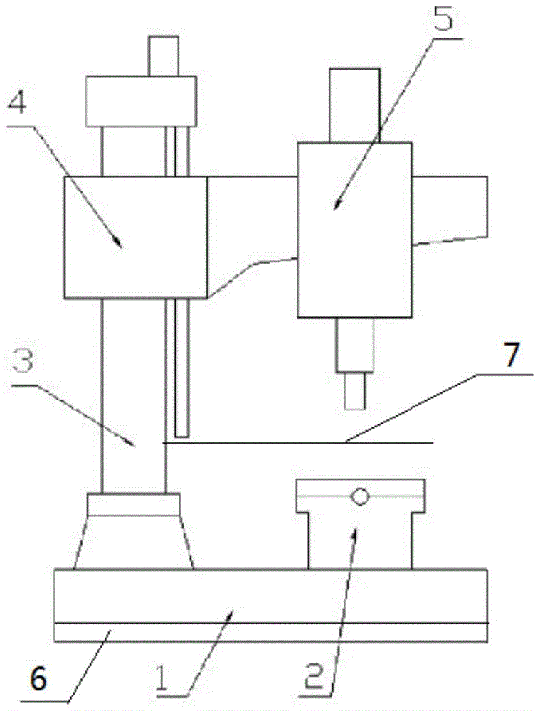
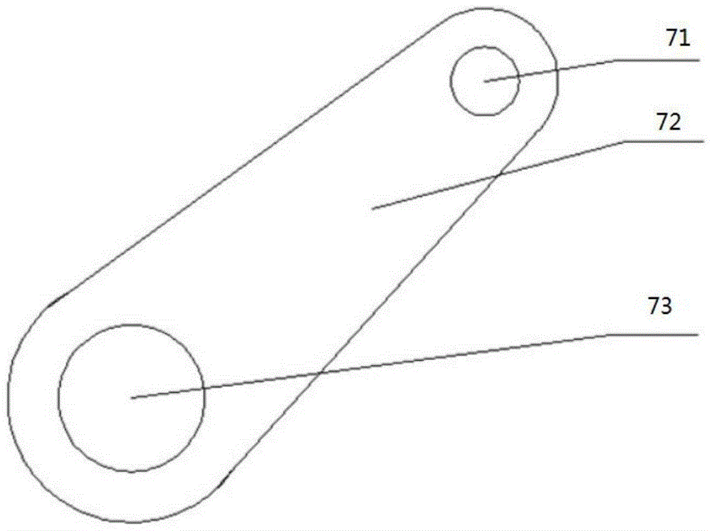
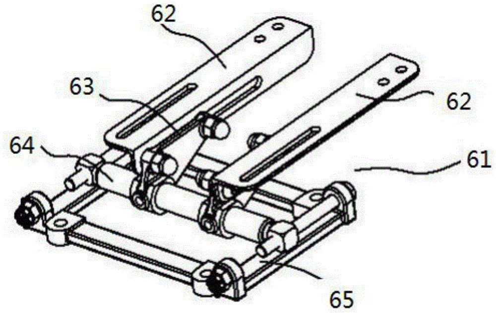
[0018] Such as Figure 1 to Figure 5 As shown, a machining drilling machine includes a fixed workbench 1, a column 3, a rocker arm 4, and a power head 5, and also includes a sliding workbench 2, a drill baffle 7, and an adjustable base 6. The sliding workbench vertically fixes the drilling machine The workbench is fixed, the head of the baffle body is provided with a swarf hole for the drill bit to pass through, and the tail is provided with a mounting hole. The head of the baffle body is wider than the tail, and the drill baffle is connected to the drilling machine through the mounting hole;

[0019] The adjustable base 6 is used to support the support plate 62 of the fixed workbench and the base 65 located below t...


PUM


Abstract

The invention relates to a machining drilling machine. The machining drilling machine comprises a fixed workbench, a stand column, a rocker arm and a power head, and further comprises a sliding workbench, a drill bit baffle and an adjustable base. The sliding workbench is perpendicularly fixed to the fixed workbench of the drilling machine. A scrap blocking hole which a drill bit can penetrate through is formed in the head portion of a baffle body. A mounting hole is formed in the tail portion of the baffle body. The head portion of the baffle body is wider than the tail portion. The drill bit baffle is connected with the drilling machine through the mounting hole. The adjustable base is fixed to the bottom of the fixed workbench. Through a supporting plate which can be adjusted horizontally and a guide barrel which can be adjusted in the circumferential direction of the adjustable base, appropriate machining angles can be adjusted freely in the horizontal direction and the circumferential direction on the whole drilling machine, so that working radii of common drilling machines are improved greatly; the drill bit baffle can completely eradicate the situation that iron scrap scatters all over the ground when the drilling machine works, so that potential safety hazards are eliminated, and economic loss is reduced.

Description

technical field [0001] The invention relates to a mechanical processing drilling machine, which belongs to the field of mechanical processing equipment. Background technique [0002] Drilling machine is a kind of common drilling equipment, and the base of existing drilling machine is fixed, when the workpiece that needs drilling is too large or when drilling angle is inclined, this drilling machine just shows powerless. In addition, when the existing drilling machine automatically feeds and drills the workpiece, sometimes the iron filings cannot be cut off, and it will rotate with the drill bit, causing the cutting fluid to fly all over the place. In serious cases, if the iron filings are too long, they will be easily thrown onto people, posing a safety hazard. At the same time, if the excessively long iron filings are entangled in the main shaft, the main shaft will not work or even be damaged, which will cause serious economic losses. Contents of the invention [0003] ...

Claims


Application Information

Patent Timeline
Patent Type & Authority Patents(China)
IPC IPC(8): B23B39/12B23Q3/04B23Q11/08
CPCB23B39/00B23Q1/25B23Q11/08
Inventor 肖杰刘东升徐平
Owner 沅陵县向华电子科技有限公司
Learn More