Cantilever joint clamping manipulator

A manipulator and clamping technology, which is applied in the field of manipulators, can solve problems such as low clamping efficiency, poor clamping stability, and large size, and achieve the effects of high stability and flexibility, increasing the radius of the working range, and enhancing safety performance

Inactive Publication Date: 2016-12-07
ZHEJIANG XINYUE MACHINE TOOL CO LTD
View PDF8 Cites 3 Cited by
  • Summary
  • Abstract
  • Description
  • Claims
  • Application Information

AI Technical Summary

Problems solved by technology

However, the auxiliary loading and unloading mechanism widely used on gear rubbing machines is too large, which affects the layout of the production line in the workshop. At the same time, it can only move in two dimensions, front and rear, and up and down, which largely interferes with the main tool of the gear rubbing machine. Moreover, the structural design of the fixture part is irrational, resulting in low clamping efficiency and poor clamping stability.

Method used


Image

  • Cantilever joint clamping manipulator
  • Cantilever joint clamping manipulator
  • Cantilever joint clamping manipulator

Examples


Embodiment Construction

[0027] Below in conjunction with accompanying drawing, the present invention will be further described with specific embodiment,

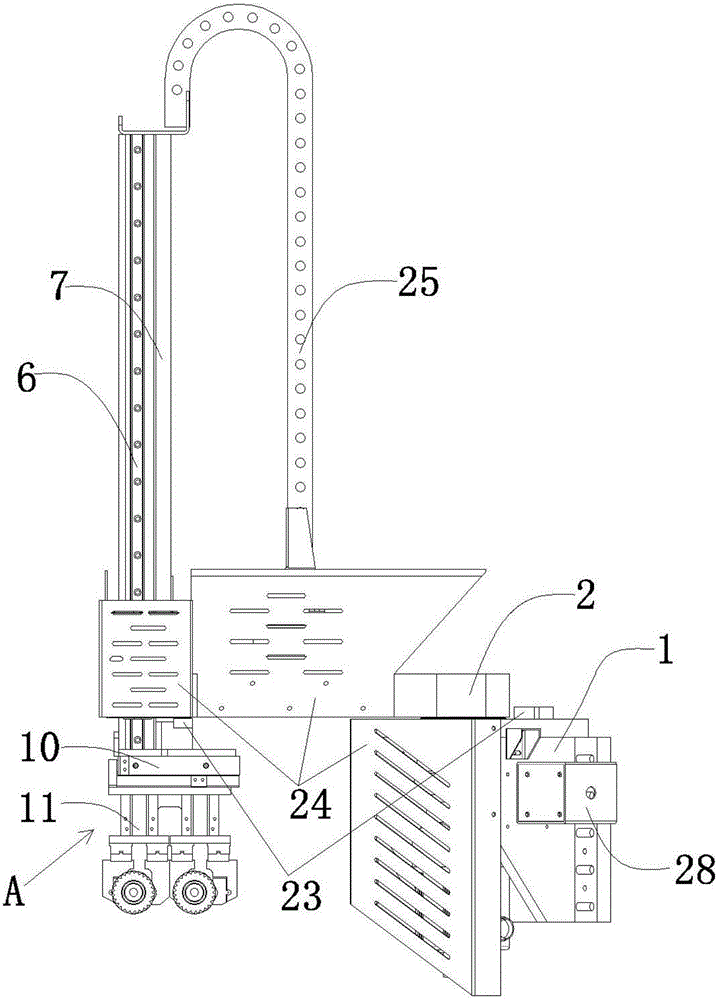
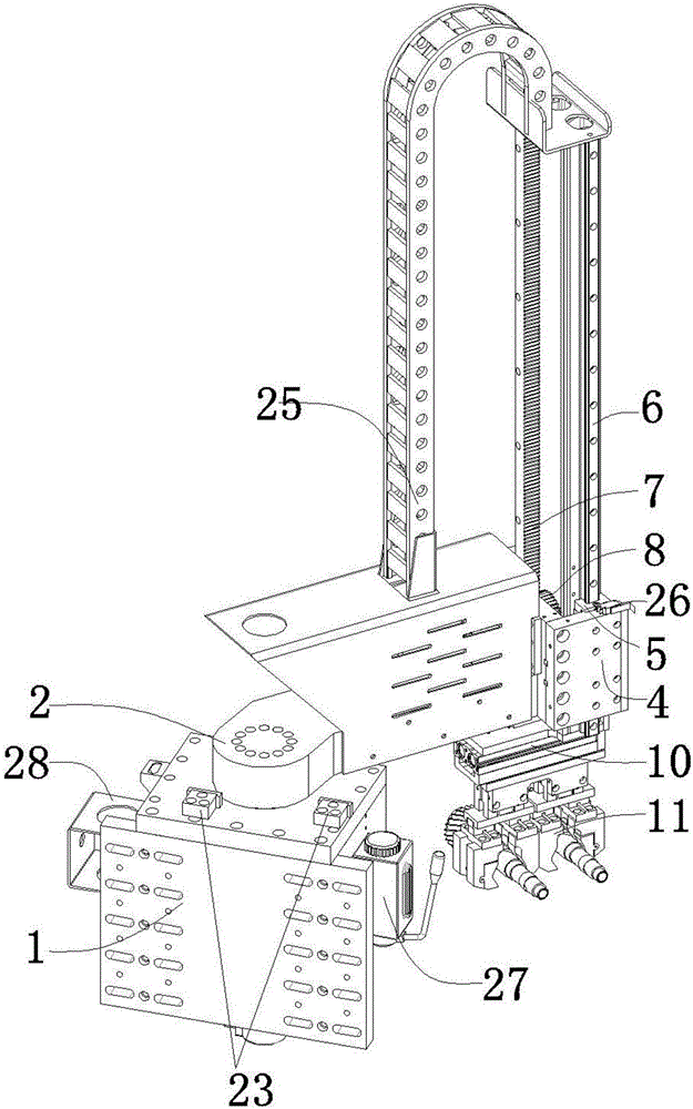
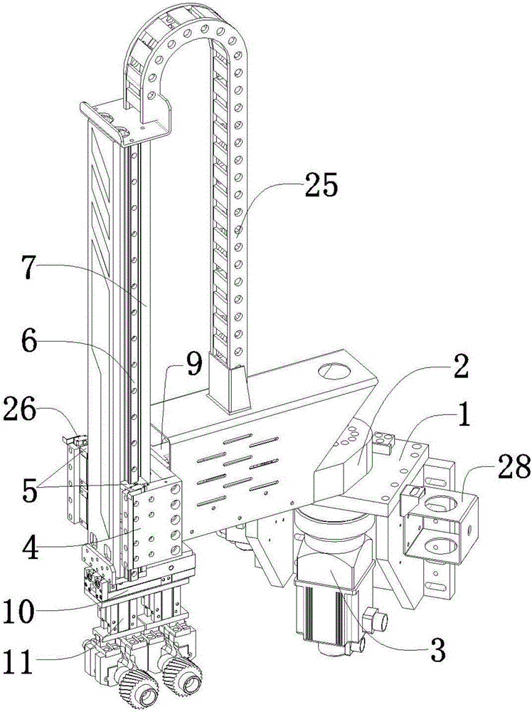
[0028] Such as Figure 1-Figure 3 As shown, a cantilever joint clamping manipulator includes a fixed plate base 1 installed on a gear rubbing machine, a rotating arm 2 is rotatably connected above the fixed plate base 1, and a device for driving the rotating arm 2 to rotate is arranged under the fixed plate base 1. The driving device 3; the left end of the rotating arm 2 is connected with a slider fixing seat 4, and the inner wall of the two sides of the slider fixing seat 4 is provided with a fixed slider 5, and a linear guide rail 6 matching it is installed on the fixed slider 5 , a rack 7 is vertically arranged on the side wall of the linear guide rail 6, a gear 8 meshing with the rack 7 is arranged on the inner wall of the side plate of the slider holder 4, and a servo motor 9 on one side of the slider holder 4 The gear 8 is driven to rotate; ...


PUM


Abstract

The invention belongs to the field of manipulators, and particularly relates to a cantilever joint clamping manipulator. The cantilever joint clamping manipulator comprises a fixed plate seat mounted on a gear rolling machine, wherein the upper side of the fixed plate seat is connected with a rotating arm in a rotatable manner; a servo motor I for driving the rotating arm to rotate is arranged below the fixed plate seat; the left end of the rotating arm is connected with a sliding block fixing seat; fixed sliding blocks are arranged o the inner walls of two side plates of the sliding block fixing seat; linear guide rails matched with the fixed sliding blocks are mounted on the fixed sliding blocks; racks are vertically arranged on the side walls of the linear guide rails; gears meshed with the racks are arranged on the inner walls of the side plates of the sliding block fixing seat; the servo motor on one side of the sliding block fixing seat drives the gears to rotate; and a workpiece switching mechanism and a workpiece clamping mechanism are connected below the linear guide rails in sequence. Due to the rotation of the rotating arm and the up-and-down lifting of the linear guide rails, three-dimensional movement of the manipulator can be realized; and furthermore, the space occupation is greatly optimized, and tool assembling of a gear rolling machine main unit cannot be interfered.

Description

technical field [0001] The invention belongs to the field of manipulators, in particular to a cantilever joint clamping manipulator. Background technique [0002] With the development of science and technology and the progress of society, gear rolling machines are widely used in metal processing and other industries. In the process of cold rolling of splines, quite a lot of manual or auxiliary machines with their own simple configuration are used. The workpiece to be processed is sent to the workpiece clamping mechanism, which is easy to cause injury to the operator. It not only increases the labor intensity of workers, but also has low production efficiency, poor positioning accuracy and poor reliability. [0003] At present, a few matching manipulators that have appeared can replace manual operations, realize mechanization and automation of production, ensure the safety of operators, and significantly increase labor productivity. However, the auxiliary loading and unload...

Claims


Application Information

Patent Timeline
Patent Type & Authority Applications(China)
IPC IPC(8): B25J9/02B25J9/12B21H9/00B25J19/06B25J15/08
Inventor 赵亚飞魏全跃
Owner ZHEJIANG XINYUE MACHINE TOOL CO LTD
Why Eureka
Try Eureka