Moving deck positioning guide rail device

A technology for positioning guide rails and movable decks, which can be applied to detachable decks and other directions, and can solve the problems of easy displacement of movable decks, affecting the positioning effect of movable decks, and damage to bulkhead rails.

Active Publication Date: 2014-11-19
ZHEJIANG OCEAN UNIV
View PDF6 Cites 2 Cited by
  • Summary
  • Abstract
  • Description
  • Claims
  • Application Information

AI Technical Summary

Problems solved by technology

[0003] The purpose of the present invention is to solve the problem in the prior art that the movable deck is easy to shift, which affects the positioning effect of the movable deck or causes damage to the bulkhead track, and provides a movable deck positioning guide rail device that can conveniently fix the movable deck
[0004]

Method used


Image

  • Moving deck positioning guide rail device
  • Moving deck positioning guide rail device
  • Moving deck positioning guide rail device

Examples


Embodiment 1

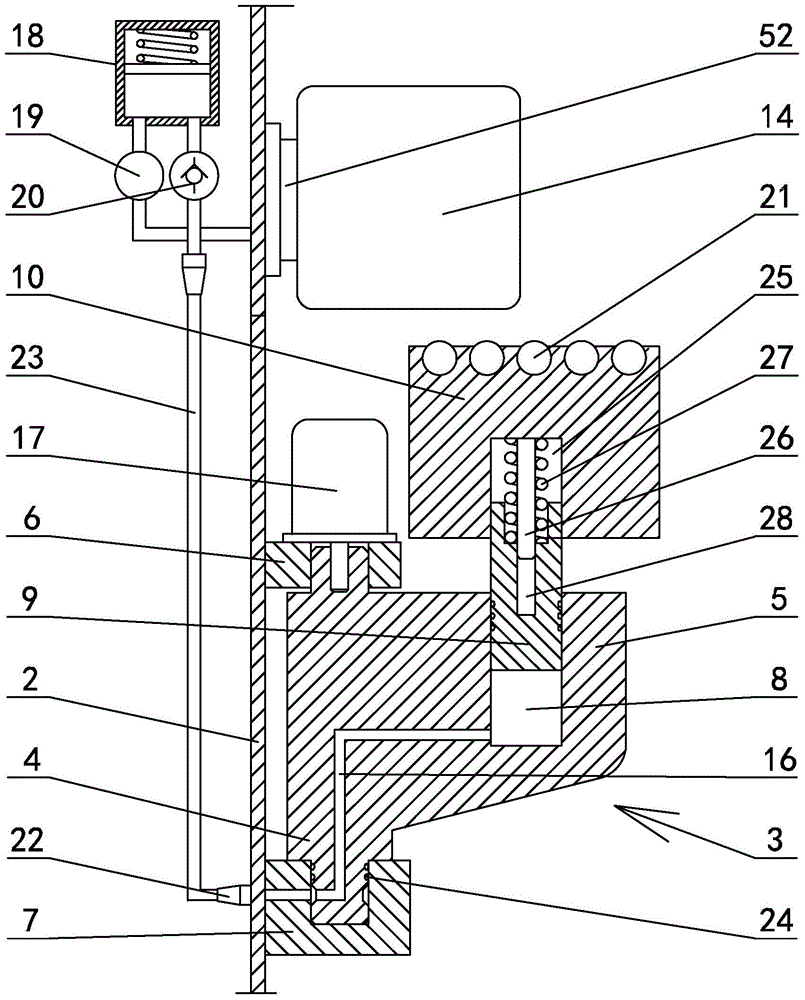
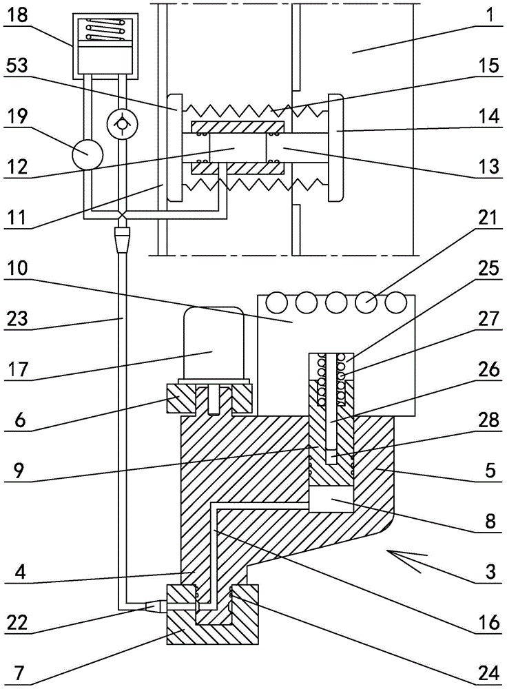
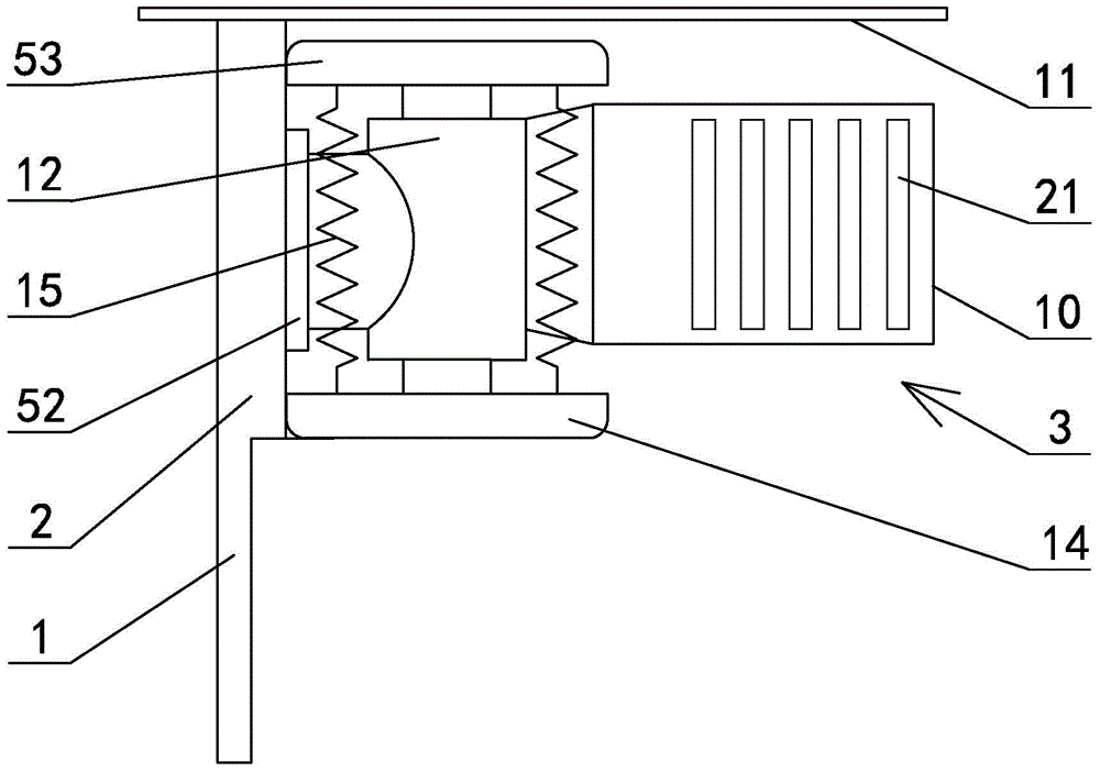
[0036] exist Figure 14In the shown embodiment 1, a movable deck positioning guide rail device is arranged on the bulkhead of a multi-purpose ship, including four strip-shaped guide rail frames fixed on the bulkhead and perpendicular to the bottom plate of the cabin, and the cross section is L-shaped. The movable deck positioning guide rail 1 is fixed on the side of the guide rail frame away from the bulkhead and parallel to the guide rail frame. The support constitutes a support structure that can support three layers of movable decks. The corbel supports used to support the same movable deck on different rail frames are arranged at the same height. The support body 5 on one side of the pivot shaft (see figure 1 ), the upper and lower ends of the pivot shaft are respectively connected to the upper pivot seat 6 and the lower pivot seat 7, the upper pivot seat and the lower pivot seat are connected to the rail frame, and the support body is provided with a lower shaft whose ax...

Embodiment 2

[0039] The corbel support and upper oil cylinder of embodiment 2 are arranged on the guide rail frame through the synchronous lifting mechanism (see Figure 5 ), the lifting mechanism includes a corbel support lifting guide rail 29 arranged on the guide rail frame and parallel to the guide rail frame and a corbel support drive box 30 arranged on the corbel support lift guide rail, and the corbel support drive box is L-shaped as a whole , the cross-section of the corbel support lifting guide rail is cross-shaped (see Figure 10 , Figure 11 ), including the fixed plate 31 and the limit strips 32 symmetrically arranged on both sides of the fixed plate, one side of the fixed plate is fixed on the guide rail frame between the movable deck positioning guide rail and the bulkhead, and the other side of the fixed plate is There are tooth grooves 33, and the limit chute 34 is formed between the limit strips on both sides of the fixed plate, the fixed plate and the guide rail frame; t...

Embodiment 3

[0043] The movable deck positioning guide rail below the second layer of corbel support in embodiment 3 is provided with a guide slide plate, and the upper end of the movable deck positioning guide rail is provided with a guide part 49 bent toward the bulkhead side, and the guide slide plate is composed of 2-4 The guide assemblies are connected successively to form, and the present embodiment is 3 (see Figure 6 ), the cross-section of the guide assembly is L-shaped, and is composed of a left slide plate 44 and a right slide plate 45 that are articulated with the two inner surfaces of the movable deck positioning guide rail respectively. The left slide plate and the right slide plate face one side of the movable deck positioning guide rail A roller groove perpendicular to the movable deck positioning guide rail is provided, and rollers are arranged in the roller groove, and the outer edges of the left slide plate and the right slide plate are bent to form a positioning groove 4...


PUM


Abstract

The invention discloses a moving deck positioning guide rail device comprising four guide rail racks in strip shapes. Each guide rail rack is provided with two to four brackets. The brackets on the four guide rail racks form a support structure capable of supporting two to four moving decks. Each bracket comprises a pivoting shaft parallel to the guide rail racks and a support member arranged on one side of the pivoting shaft; upper and lower pivoting blocks connected through the pivoting shaft are connected with the corresponding guide rail rack; a lower cylinder having the axis parallel to the corresponding guide rail rack is disposed inside the support member; the upper end of a piston of the lower cylinder is connected with a support block; an upper cylinder having the axis perpendicular to the surface of a bin wall is arranged over each bracket; the outer end of a piston of each upper cylinder is connected with front and rear ejector blocks, and a tension spring is arranged between the front ejector block and the rear ejector block; the bottom of the lower cylinder is communicated with the upper cylinder through a hydraulic pipe. By the use of the moving deck positioning guide rail device, the problem of the prior art that the moving decks easily shift so that desk positioning effect is affected or damage of bin rails is caused is effectively solved; the moving deck positioning guide rail device has high practical value.

Description

technical field [0001] The invention relates to the technical field of shipbuilding, in particular to a movable deck positioning guide rail device. Background technique [0002] The bulkhead track on a multi-purpose ship can be used to fix the multi-layer movable deck, and the four corners of the movable deck are limited by the track composed of four angle steels to prevent the movable deck from moving in the cabin; when the multi-purpose ship needs to transport dense When goods such as steel, steel plates, steel coils and other goods, these bulky goods can only be placed on the bottom of the hold. After the cargo at the bottom of the cabin is placed, use the support of four contoured corbels set on the four bulkhead rails to place the movable deck overhead on the bulkhead rails of the multi-purpose ship. At this time, the bottom surface of the movable deck and the bottom of the cabin The space between them is used to load steel, steel plates, steel coils and other goods, a...

Claims


Application Information

Patent Timeline
IPC IPC(8): B63B25/18
Inventor 陈正寿孙孟
Owner ZHEJIANG OCEAN UNIV
Why Eureka
Try Eureka