Airlift type integrated sewage treatment device

A sewage treatment device, air-lifting technology, applied in the field of air-lifting integrated sewage treatment device, can solve the problems that anaerobic microorganisms cannot play their role better, increase equipment cost and operating cost, and affect the effect of sewage treatment, etc. Achieve the effect of high sewage treatment efficiency, simple structure, and reduce dead angle of water flow

Active Publication Date: 2014-11-19
YUNNAN HEXUN ENVIRONMENTAL TECH CO LTD
View PDF8 Cites 20 Cited by
  • Summary
  • Abstract
  • Description
  • Claims
  • Application Information

AI Technical Summary

Problems solved by technology

[0003] The sludge concentration in the integrated sewage treatment equipment is usually maintained at a relatively high level, which easily leads to low oxygen transfer rate, large operating energy consumption, high water temperature and low sludge activity.
In order to remove nitrate nitrogen, the existing integrated equipment needs to return the nitrifying liquid from the aerobic tank to the anoxic tank. Sludge returns to the pre-denitrification tank, so it is often necessary to install nitrifying liquid return pumps and sludge return pumps, and install corresponding solenoid valves at the same time, which not only increases equipment costs and later operating costs, but also increases equipment failure points. Not conducive to equipment maintenance
In addition, the liquid in the anaerobic tank of the existing integrated sewage treatment equipment usually has the problem of high dissolved oxygen, so that the anaerobic microorganisms in the anaerobic tank cannot play their role better, affecting the effect of sewage treatment

Method used


Image

  • Airlift type integrated sewage treatment device
  • Airlift type integrated sewage treatment device
  • Airlift type integrated sewage treatment device

Examples


Embodiment

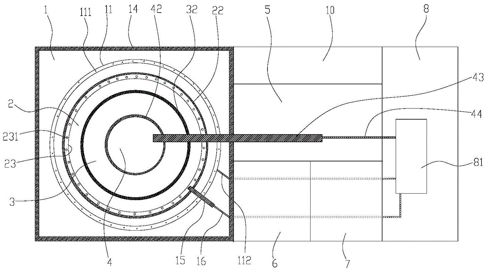
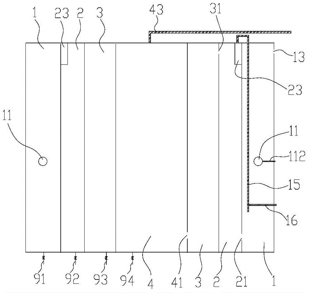
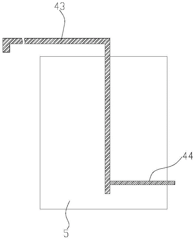
[0025] refer to Figure 1-7 , the air-lift integrated sewage treatment device provided in this embodiment includes a housing, a regulating tank 10, a pre-denitration tank 4, an anaerobic tank 3, an anoxic tank 2, an aerobic tank 1, a sedimentation tank 5, and a sludge tank 6 And clean water pool 7, and equipment control room 8. The regulating pool 10, the pre-denitration pool 4, the anaerobic pool 3, the anoxic pool 2, the aerobic pool 1, and the sedimentation pool 5 are arranged in the shell and communicated in sequence. The sludge tank 6 and the clean water tank 7 are also arranged in the shell, and communicate with the sedimentation tank 5 respectively.

[0026] The regulating tank 10 is provided with a water outlet and a water inlet, and a water inlet valve is arranged at the water inlet, and the water inlet is connected with an external sewage source through a pipeline. The sewage is subjected to conventional preliminary treatment, such as separating solid waste through...


PUM


Abstract

The invention relates to the technical field of sewage treatment, and specifically relates to an airlift type integrated sewage treatment device. The airlift type integrated sewage treatment device comprises an adjusting tank, an anaerobic tank, an anoxic tank, an aerobiotic tank and a sedimentation tank which are installed in a shell and are communicated in sequence. The aerobiotic tank is provided with an aerator pipe and a first airlift mechanism; the first airlift mechanism comprises a first air inlet and a first lifting pipe; an inlet of the first lifting pipe extends to a medium-lower part of the aerobiotic tank; the first an outlet of the first lifting pipe is communicated with the anoxic tank; the first airlift inlet pipe is communicated with the first lifting pipe; both the aerator pipe and the first air inlet pipe are connected to a draught fan; and a meshy deoxidization frame matching with a cross section of the aerobiotic tank is disposed in the aerobiotic tank and above a water inlet of the aerobiotic tank. The first airlift mechanism, a second airlift mechanism and the aerator pipe are sent air by the same draught fan, thereby reducing components in the device, reducing cost of the device, simplifying the structure of the device and facilitating maintenance of the device. A liquid and sludge are refluxed in an airlift manner, so that energy consumption of the device can be reduced and operation cost is reduced.

Description

technical field [0001] The invention relates to the technical field of sewage treatment, in particular to an air-lift integrated sewage treatment device. Background technique [0002] According to statistics, the total amount of sewage discharge in my country has reached 62 billion tons, most of which are directly discharged into rivers and lakes without treatment. Nearly a quarter of the lakes have been polluted to varying degrees, and nearly 60% of them There are no sewage treatment plants in cities and towns, and domestic sewage in rural areas is basically discharged directly without treatment. With the continuous advancement of rural urbanization, more than 80% of domestic sewage will come from rural areas and cities in the future. In 2013, my country's rural and urban domestic sewage discharge has reached 30 billion m 3 , and a large amount of scattered domestic sewage has caused serious pollution to underground drinking water sources, surface runoff, and farmland soil...

Claims


Application Information

Patent Timeline
Patent Type & Authority Applications(China)
IPC IPC(8): C02F9/14
Inventor 裴廷权周洪昌李文生梅峰何海波周岗泉张松涛王智雄
Owner YUNNAN HEXUN ENVIRONMENTAL TECH CO LTD
Why Eureka
Try Eureka