Waterproof construction method for anti-floating anchor rods
A technology of anti-floating anchor rods and construction methods, which is applied in infrastructure engineering, protection devices, buildings, etc., can solve the problems of long capillary water path, sealing unable to block water gushing points, and remaining hidden dangers of water seepage, etc., and achieves good water stop effect , Solve the problem that the waterproof coating is not tight and easy to seep, and improve the leakage resistance
- Summary
- Abstract
- Description
- Claims
- Application Information
AI Technical Summary
Problems solved by technology
Method used
Image
Examples
Embodiment 1
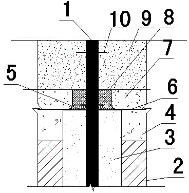
[0020] The anti-floating anchor rod waterproof construction method of the present invention comprises the following construction steps:
[0021] A. Clean the surface of the anti-floating anchor rod 1, put it vertically into the underground soil layer 2, and pour a concrete cushion 4 on the underground soil layer 2;
[0022] B. Pour cement paste 3 around the anti-floating anchor rod 1. The pouring height of cement paste 3 is the sum of the height of underground soil layer 2 and concrete cushion 4; Grout, do not shake anti-floating anchor rod 1 within 24 hours after grouting;
[0023] C. Clean the upper surface of the cement slurry 3 and the concrete cushion 4 within a radius of 250mm with the anti-floating anchor 1 as the center point, and paint the cement-based crystalline waterproof coating 5 three times, and the key painting part is the anti-floating anchor 1 and the junction of the concrete cushion 4;
[0024] D. After the cement-based crystalline waterproof coating 5 is ...
Embodiment 2
[0032] The anti-floating anchor rod waterproof construction method of the present invention comprises the following construction steps:
[0033] A. Clean the surface of the anti-floating anchor rod 1, put it vertically into the underground soil layer 2, and pour a concrete cushion 4 on the underground soil layer 2;
[0034] B. Pour cement paste 3 around the anti-floating anchor rod 1. The pouring height of cement paste 3 is the sum of the height of underground soil layer 2 and concrete cushion 4; Grout, do not shake anti-floating anchor rod 1 within 24 hours after grouting;
[0035] C. Clean the upper surface of the cement slurry 3 and the concrete cushion 4 within a radius of 300mm with the anti-floating anchor 1 as the center point, and paint the cement-based crystalline waterproof coating 5 three times, and the key painting part is the anti-floating anchor 1 and the junction of the concrete cushion 4;
[0036] D. After the cement-based crystalline waterproof coating 5 is ...
Embodiment 3
[0044] The anti-floating anchor rod waterproof construction method of the present invention comprises the following construction steps:
[0045] A. Clean the surface of the anti-floating anchor rod 1, put it vertically into the underground soil layer 2, and pour a concrete cushion 4 on the underground soil layer 2;
[0046] B. Pour cement paste 3 around the anti-floating anchor rod 1. The pouring height of cement paste 3 is the sum of the height of underground soil layer 2 and concrete cushion 4; Grout, do not shake anti-floating anchor rod 1 within 24 hours after grouting;
[0047] C. Clean the upper surface of the cement slurry 3 and the concrete cushion 4 within a radius of 350mm with the anti-floating anchor 1 as the center point, and paint the cement-based crystalline waterproof coating 5 three times, and the key painting part is the anti-floating anchor 1 and the junction of the concrete cushion 4;
[0048] D. After the cement-based crystalline waterproof coating 5 is ...
PUM
| Property | Measurement | Unit |
|---|---|---|
| Thickness | aaaaa | aaaaa |
| Thickness | aaaaa | aaaaa |
| Height | aaaaa | aaaaa |
Abstract
Description
Claims
Application Information
 - R&D
- Intellectual Property
- Life Sciences
- Materials
- Tech Scout
- Unparalleled Data Quality
- Higher Quality Content
- 60% Fewer Hallucinations
Browse by: Latest US Patents, China's latest patents, Technical Efficacy Thesaurus, Application Domain, Technology Topic, Popular Technical Reports.
© 2025 PatSnap. All rights reserved.Legal|Privacy policy|Modern Slavery Act Transparency Statement|Sitemap|About US| Contact US: help@patsnap.com

