Testing device and testing method of pile composite foundation combined with broken stone hardcore foundation

A technology of composite foundation and gravel cushion is applied in the field of structural shock absorption and earthquake resistance, which can solve the problems of waste of resources, increase of cost, and reduction of horizontal seismic shear force.

Inactive Publication Date: 2014-11-19
SOUTHEAST UNIV
View PDF5 Cites 11 Cited by
  • Summary
  • Abstract
  • Description
  • Claims
  • Application Information

AI Technical Summary

Problems solved by technology

The usual anti-seismic technology route is to increase the burial depth of bridges and structural foundations, and increase the dimensional stiffness of structural members, but this method not only increases the cost but also brings a lot of waste of resources. For this reason, the academic community has proposed a A new foundation form, this foundation form comprehensively adopts pile co...

Method used


Image

  • Testing device and testing method of pile composite foundation combined with broken stone hardcore foundation
  • Testing device and testing method of pile composite foundation combined with broken stone hardcore foundation
  • Testing device and testing method of pile composite foundation combined with broken stone hardcore foundation

Examples


Embodiment 1

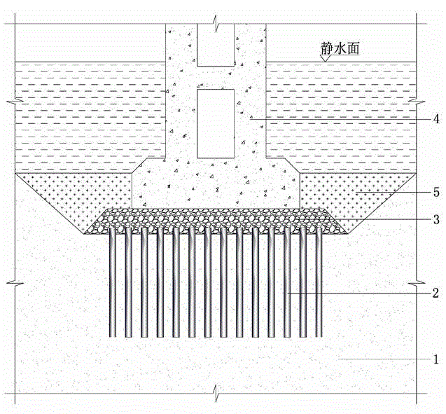
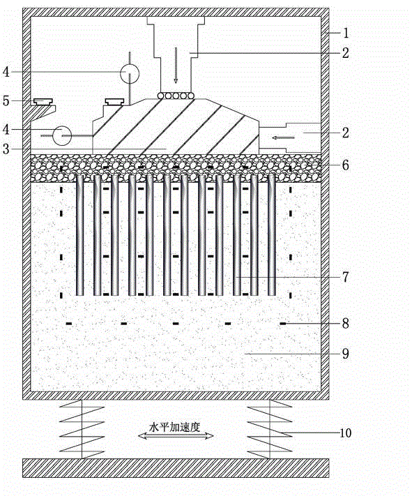
[0031] like figure 2 As shown, this embodiment adopts a seismic station full-model dynamic test device in the foundation form of a pile composite foundation and a gravel cushion. The device includes a model box 1, a reaction frame 1, a loading device 2, a rigid cap model 3, a displacement sensor 4, an acceleration sensor 5, a gravel cushion model 6, a pile composite foundation model 7, a strain gauge 7, and an earth pressure sensor 8. Sand 9, seismic station 10, etc. Model box 1 is an upper open box, and sand 9 is filled in the box, and model piles 7 are driven into sand 9 to form a pile composite foundation, and the top of the model pile is higher than the top of the sand After the pile composite foundation is formed, a cushion layer 6 simulated by sand is laid on it, and a rigid cap 3 is arranged on the cushion layer 6, and a loading device 2 is arranged on the cap, and there is a sliding device between the cap and the loading device. , the earth pressure sensor 8 is set i...

Embodiment 2

[0041] like Figure 4 As shown, the present embodiment adopts PIV camera semi-model static test device. The main difference with Embodiment 1 is: the basic model only takes half of the full model test model, and a facade of the model test container is made of transparent plexiglass, and a camera 11 for PIV shooting is installed outside the plexiglass, and the test does not need a seismic table and acceleration Displacement gauge.

[0042] The PIV video camera semi-model static test specifically includes the following steps:

[0043] (1) Put the sand 9 into the model box 1 in layers. In order to ensure the homogeneity of the soil, the thickness of each layer is controlled within 2 times the pile diameter. After compaction, continue to lay the sand 9, and lay the sand to the predetermined depth , it is necessary to place an earth pressure gauge 8 at the position shown in the figure. After the sand is laid, insert the model pile 7 with a strain gauge on the inside into the sand...


PUM


Abstract

The invention discloses a testing device and testing method of a pile composite foundation combined with a broken stone hardcore foundation. A seismostation full-model dynamic test focuses on researching the displacement, strain and acceleration changes of the foundation form under the action of horizontal dynamic loading, and the dynamic response, the failure mode and the shock absorption characteristic of the foundation form are analyzed and researched. The foundation form is researched by a PIV camera half-model static test in a macroscopic, microcosmic and multiscale mode, the displacement, strain and other responses of the foundation under the action of horizontal and vertical static loading are researched macroscopically, and the bearing mechanism and the failure mode of the foundation form are microcosmically analyzed in the aspect of the particle size according to particle displacement, rotation, the local porosity and other microcosmic parameters. The dynamic model test and the static model test are comprehensively applied, the bearing mechanism and the failure mode of the foundation form can be visually inspected, the shock absorption effect of the foundation form is effectively analyzed, the wider research of the academic world on the foundation form is promoted, and the foundation form can be applied to practical engineering as soon as possible.

Description

technical field [0001] The invention relates to research and analysis in the field of shock absorption and anti-seismic structures, in particular to a test device and a test method for a pile composite foundation combined with a crushed stone cushion foundation. Background technique [0002] Bridges and structural engineering are expensive and have huge social functions. Their safety and durability are very important, and earthquakes are one of the main reasons for the damage of such structures. At present, domestic and foreign researches on large-scale bridge and structural anti-seismic shock absorption technology are not only a hot spot but also face many difficulties to be solved. As the span of bridges and the volume of building structures become larger and larger, they are more sensitive to the vibration effects caused by earthquakes. The usual anti-seismic technology route is to increase the burial depth of bridges and structural foundations, and increase the dimension...

Claims


Application Information

Patent Timeline
IPC IPC(8): E02D33/00
Inventor 赵学亮南文文龚维明
Owner SOUTHEAST UNIV
Why Eureka
Try Eureka