
System and Method for Injector Fault Remediation

A technology for injectors and faults, which is applied in the direction of machines/engines, electronic control of exhaust treatment devices, and diagnostic devices for exhaust treatment devices, etc. and mechanical hardware

Inactive Publication Date: 2014-11-19
CATERPILLAR INC
View PDF6 Cites 5 Cited by
  • Summary
  • Abstract
  • Description
  • Claims
  • Application Information

AI Technical Summary

Problems solved by technology

In known urea injection systems, challenges related to temperature and / or pressure can arise which affect the electrical and mechanical hardware used to inject urea
Considering, for example, that urea is usually injected directly into an engine's exhaust system in the form of an aqueous solution, changes in solution concentration due to thermal or pressure effects can hamper the injector during system operation and after thermal saturation following a hot engine shutdown normal work
Also, for systems using water-based urea solutions, depressurization and / or boiling of the system can cause urea to crystallize at the injector, which can clog the injector

Method used


Image

  • System and Method for Injector Fault Remediation
  • System and Method for Injector Fault Remediation
  • System and Method for Injector Fault Remediation

Examples


Embodiment Construction

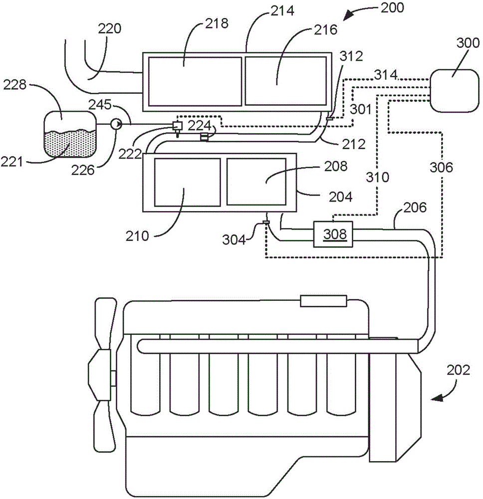
[0014] The present invention relates to power management systems for machines, and more particularly to power management systems and methods for preventing and, if necessary, remediating DEF injector clogging due to urea crystallization.

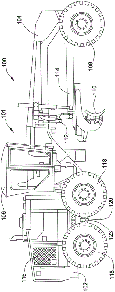
[0015] figure 1 A side view of a machine 100, which in this example is a motor grader 101, is shown in . The term "machine" is generally used to describe any machine having at least one drive wheel driven directly by a motor connected to the drive wheel, for example electrically or hydrostatically, or alternatively by mechanical means via an engine via a transmission . although figure 1 A self-propelled motor grader is shown in , but any machine performing some type of operation related to an industry such as mining, construction, farming, transportation, marine or any other industry known in the art is contemplated. For example, machine 100 may be an earth moving machine such as a wheel loader, excavator, dump truck, backhoe loader, mate...


PUM


Abstract

A machine includes an engine having an exhaust system. A diesel exhaust fluid (DEF) injector provides metered amounts of DEF and includes a valve adapted to selectively open in response to a command. A controller associated with the engine and the DEF injector monitors operation of the DEF injector to detect a fault and activates a failure remediation cycle when the fault has been detected. The remediation cycle includes heating the exhaust gas to heat the DEF injector and melt any urea crystals that may be causing the fault, and activating the valve of the DEF injector to evacuate molten urea from within the DEF injector.

Description

technical field [0001] The present invention relates generally to engine systems, and more particularly to exhaust aftertreatment systems and methods. Background technique [0002] One known method for removing certain diesel engine exhaust constituents is the use of exhaust aftertreatment systems utilizing selective catalytic reduction (SCR) of nitrogen oxides. In a typical SCR system, urea or a urea-based aqueous solution is mixed with the exhaust gas. In some applications, the urea solution is injected directly into the exhaust passage via a dedicated injector device. The injected urea solution mixes with the exhaust gas and decomposes to provide ammonia (NH 3 ). Ammonia then reacts at the catalyst with nitrogen oxides (NO X ) reaction to provide nitrogen (N 2 ) and water (H 2 O). [0003] As can be appreciated, SCR systems require some form of urea to be present near the engine system so that the engine can be continuously supplied with urea during operation. Var...

Claims


Application Information

Patent Timeline
IPC IPC(8): F01N11/00F01N3/34
CPCF01N3/2006F01N3/2066F01N2610/02F01N2610/102F01N2610/1453F01N2610/1493F01N2900/0416F01N2900/1811Y02T10/12
Inventor B·科尔M·F·法伦克鲁格J·孙
Owner CATERPILLAR INC
Learn More