Method and system for detecting malfunctioning of fluid tank of machine

a technology of fluid tank and machine, which is applied in the direction of liquid/fluent solid measurement, machines/engines, instruments, etc., can solve the problems of tank shrinkage, complex arrangement, and degradation of the performance of the after-treatment system

Inactive Publication Date: 2016-08-04
CATERPILLAR INC
View PDF2 Cites 4 Cited by
  • Summary
  • Abstract
  • Description
  • Claims
  • Application Information

AI Technical Summary

Problems solved by technology

The blockage of the cap or the breather system creates a vacuum inside the tank leading to shrinkage of the tank.
The blockage of the cap or the breather system, if left unnoticed, leads to degradation in performance of the after-treatment system.
However, such an arrangement is complex, and is expensive for conducting the tank-venting diagnosis.

Method used


Image

  • Method and system for detecting malfunctioning of fluid tank of machine
  • Method and system for detecting malfunctioning of fluid tank of machine
  • Method and system for detecting malfunctioning of fluid tank of machine

Examples


Embodiment Construction

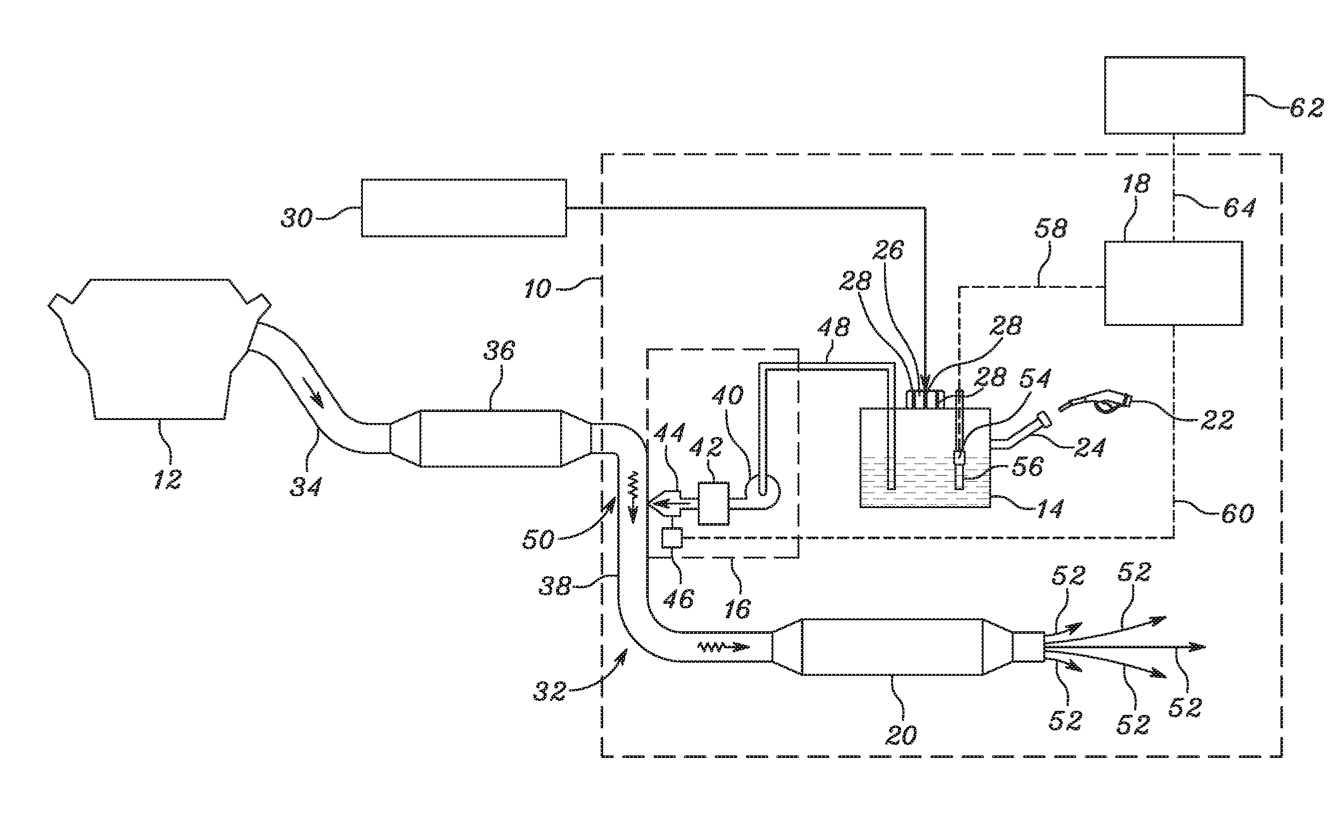
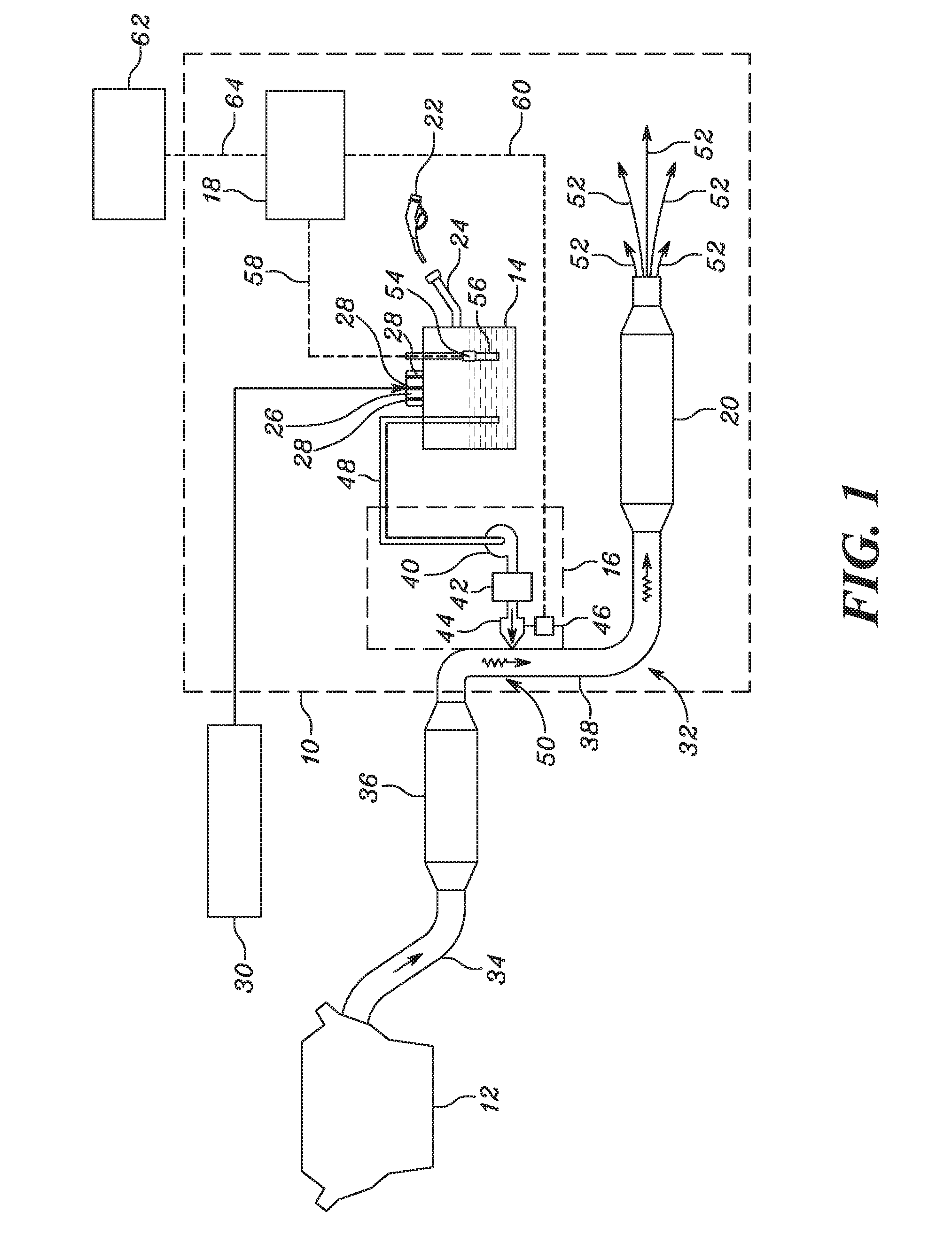
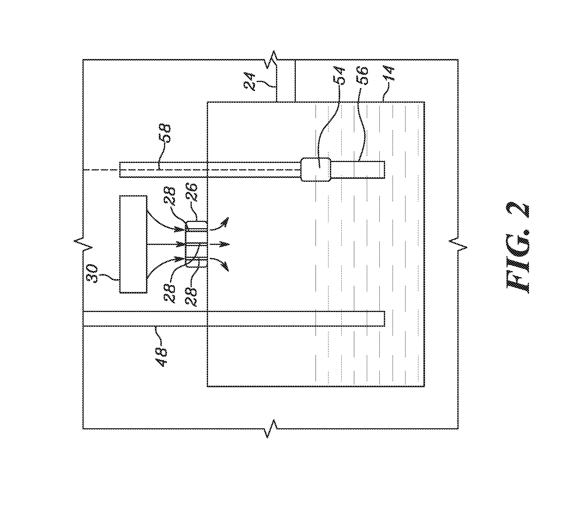
[0011]Referring to FIG. 1, a system 10 for treating exhaust of a diesel engine 12 is provided. The system 10 includes a tank 14, a dispensing system 16, a processor 18, and a catalytic converter 20. The tank 14 contains fluid and air. In an embodiment, the fluid contained in the tank 14 is a diesel exhaust fluid (DEF). The DEF is a clear non-hazardous liquid made up of a solution of about 32.5% high purity urea in de-mineralized water. The DEF is replenished in the tank 14 by a nozzle 22. The nozzle 22 is further connected to a DEF supply (not shown). The nozzle 22 dispenses the DEF into a first conduit 24 coupled to the tank 14. The tank 14 is provided with a cap 26 with a number of air passages 28 to receive air into the tank 14 from an atmosphere 30. It will be apparent to one skilled in the art that the air from the atmosphere 30 may be provided to the tank 14 by various mechanisms such as, but not limited to, the air passages 28 in the cap 26, a breather system (not shown) coup...


PUM


Abstract

A method is disclosed for detecting a malfunctioning of a tank containing fluid, using a processor and a level sensor. The processor calculates a rate of consumption of the fluid in the tank. The processor further calculates an estimated change in level of the fluid in the tank based on the rate of consumption of the fluid. The level sensor determines a measured change in level of the fluid in the tank. The processor compares the estimated change in level of the fluid with the measured change in level of the fluid. The processor further determines the malfunctioning of the tank if a difference between the estimated change in level of the fluid and the measured change in level of the fluid exceeds a predetermined value. The fluid contained in the tank is a diesel exhaust fluid.

Description

TECHNICAL FIELD[0001]The present disclosure relates to a fluid tank of a machine, and more specifically, to a method for detecting a malfunctioning of the tank containing the fluid.BACKGROUND[0002]Machines employing diesel engines generally use an after-treatment system. The after-treatment system utilizes a selective catalytic reduction (SCR) process for treating exhaust emissions. The SCR process includes reducing nitrogen oxide (NOx) emissions to nitrogen (N2), water (H2O), and carbon dioxide (CO2), by using a reducing agent, known as diesel exhaust fluid (DEF). The diesel exhaust fluid (DEF) is a clear non-hazardous liquid made up of a solution of about 32.5% high-purity urea in de-mineralized water. A small quantity of the DEF is injected into high temperature exhaust stream upstream of a SCR catalyst, where the DEF vaporizes and decomposes to form ammonia (NH3) and carbon dioxide (CO2). Further, the ammonia in conjunction with the SCR catalyst converts the (NOx) to harmless ni...

Claims


Application Information

Patent Timeline
Patent Type & Authority Applications(United States)
IPC IPC(8): F01N11/00G01F23/00F16K37/00
CPCF01N11/00F01N2550/05G01F23/00F16K37/00F01N2610/02F01N2610/1406F01N2610/144F01N2900/1812F01N2900/1814Y02T10/40
Inventor HOGAN, KEITH D.
Owner CATERPILLAR INC
Why Eureka
Try Eureka