
System, apparatus, and method to address unwanted def-based deposits in diesel exhaust system

a technology of diesel exhaust system and def-based deposits, which is applied in the direction of exhaust treatment electric control, machines/engines, separation processes, etc., can solve the problems of reducing fuel efficiency, reducing the efficiency of fuel treatment, so as to increase the heat evaporation and urea thermolysis rate, increase the heat transferring structure, and facilitate heat transfer

Active Publication Date: 2017-10-12
CATERPILLAR INC
View PDF0 Cites 6 Cited by
  • Summary
  • Abstract
  • Description
  • Claims
  • Application Information

AI Technical Summary

Benefits of technology

This patent patent describes a method and a component of a diesel exhaust system that enhance the evaporation of urea and the decomposition of urea through increased heat transfer. This is achieved by providing a surface structure on the exhaust component that comes into contact with the aqueous urea solution and the exhaust gas, allowing for faster heat transfer. This results in faster water evaporation and urea thermolysis, and improves the efficiency of the exhaust system.

Problems solved by technology

However, once the water evaporates the urea can react with itself and HNCO to form unwanted byproducts, such as biuret.
Thus, injection of DEF can form a film on surfaces of the diesel engine exhaust system that, if not suitably removed, can lead to unwanted deposit formations at various portions of the exhaust system.
The unwanted deposit formations can be difficult to remove and can also lead to reduction in fuel efficiency, filter failure, damage or blockage to an SCR catalyst, and excessive back pressure, for instance.
Additionally, the DEF can form a film in or on a hydrolysis catalyst, if such a catalyst is employed in the exhaust system, causing accumulation of urea, which can adversely impact DEF dosing control.
However, such methods can increase fuel consumption or are impractical.
However, as noted above, DEF can form a film in or on the hydrolysis catalyst causing accumulation of urea, which can adversely affect DEF dosing control.

Method used


Image

  • System, apparatus, and method to address unwanted def-based deposits in diesel exhaust system
  • System, apparatus, and method to address unwanted def-based deposits in diesel exhaust system
  • System, apparatus, and method to address unwanted def-based deposits in diesel exhaust system

Examples


Embodiment Construction

[0020]The description set forth below in connection with the appended drawings is intended as a description of various embodiments of the described subject matter and is not necessarily intended to represent the only embodiment(s). In certain instances, the description includes specific details for the purpose of providing an understanding of the described subject matter. However, it will be apparent to those skilled in the art that embodiments may be practiced without these specific details. In some instances, well-known structures and components may be shown in block diagram form in order to avoid obscuring the concepts of the described subject matter. Wherever possible, corresponding or similar reference numbers will be used throughout the drawings to refer to the same or corresponding parts.

[0021]Any reference in the specification to “one embodiment” or “an embodiment” means that a particular feature, structure, characteristic, operation, or function described in connection with...


PUM

PropertyMeasurementUnit
temperatureaaaaaaaaaa
areaaaaaaaaaaa
temperatureaaaaaaaaaa

Abstract

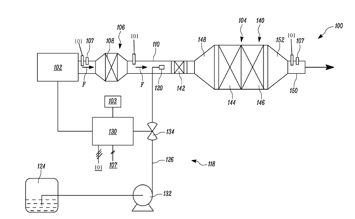
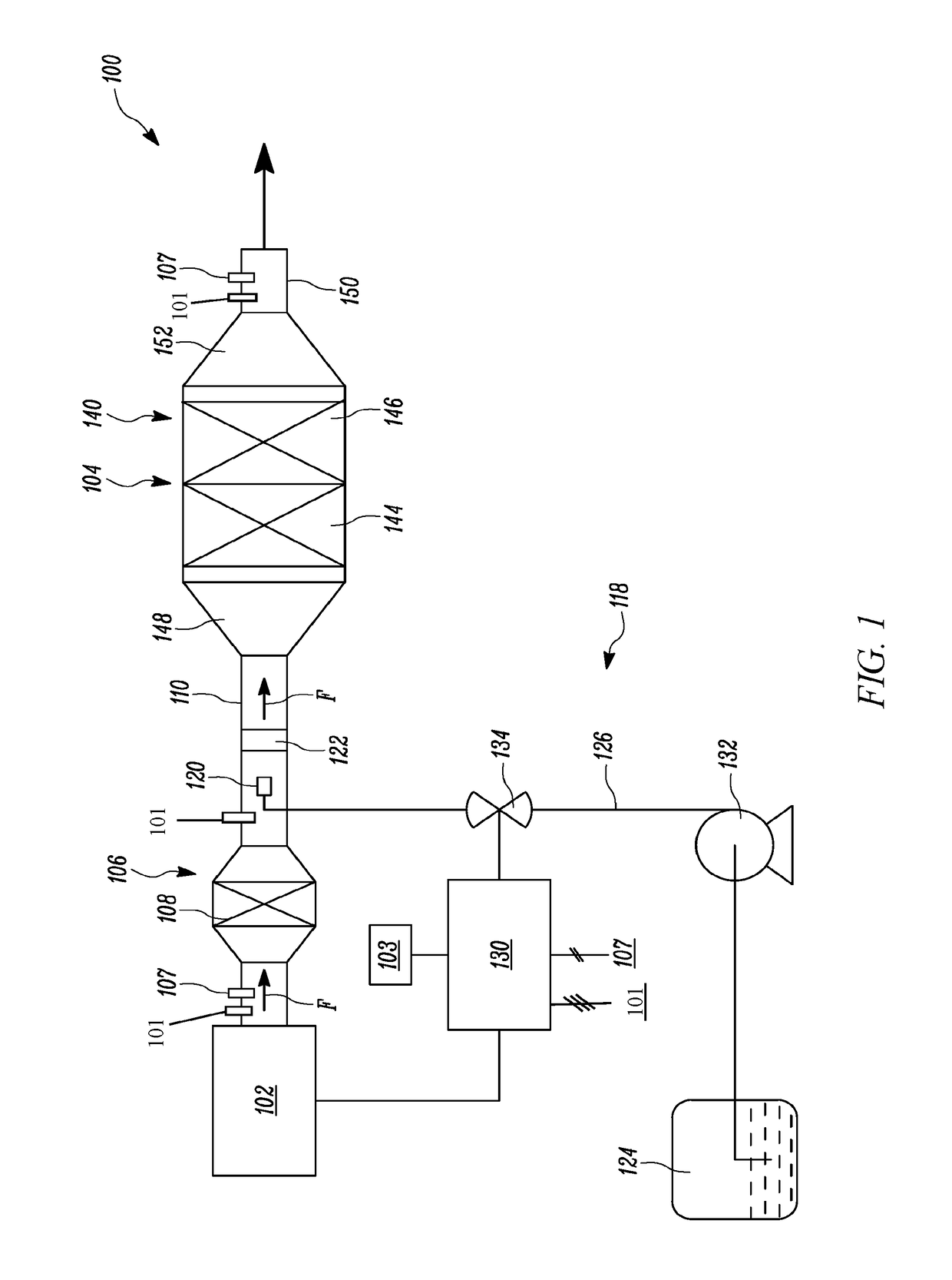
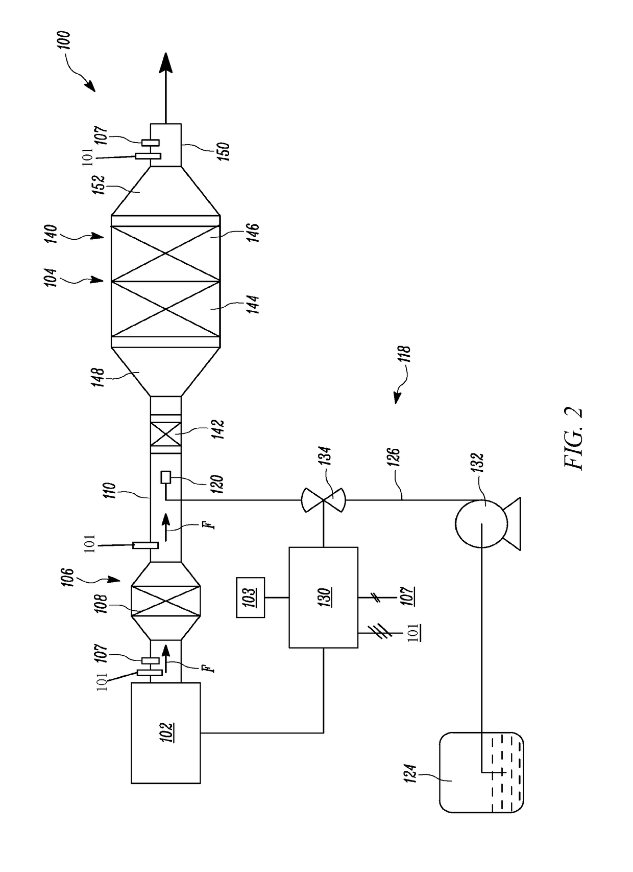
An exhaust system for a diesel engine is provided. The exhaust system includes a component body with a surface, and a surface treatment disposed on some of the surface or all of the surface. The surface treatment is disposed so as to receive Diesel Exhaust Fluid (DEF) injected into the exhaust system during operation of the diesel engine. The surface treatment facilitates increased heat transfer to the received DEF to promote water evaporation and urea thermolysis of the received DEF.

Description

TECHNICAL FIELD[0001]The present disclosure relates to an exhaust system associated with engines, particularly diesel engines, but also engines of other fuel types, such as dual fuel engines and natural gas engines.BACKGROUND[0002]Diesel engines, like most engines, can require compliance with a variety of emission standards. In order to meet emission standards, the exhaust gases exiting the diesel engine can be treated by a variety of treatments to remove or minimize unwanted aspects. An exhaust system is generally associated with a diesel engine system for treating exhaust gases to meet emission standards.[0003]Exhaust systems for diesel engines can treat and reduce oxides of nitrogen (NOx) present in exhaust gas flow, prior to the exhaust gas flow exiting into the atmosphere. For example, an aqueous urea solution made from certain percentages of urea and deionized water, such as Diesel Exhaust Fluid (DEF) (e.g., 32.5% urea and 67.5% deionized water), collectively now DEF, can be i...

Claims


Application Information

Patent Timeline
Patent Type & Authority Applications(United States)
IPC IPC(8): F01N9/00F01N3/28B01D53/94F01N3/20
CPCF01N9/00F01N3/206F01N3/2892F01N2900/1806B01D53/9495F01N2610/02F01N2610/10B01D53/9431B01D53/90B01D53/9436B01D53/9477F01N3/2066B01D2251/2062B01D2251/2067B01D2255/1021B01D2255/1023B01D2255/104B01D2255/106B01D2255/20738B01D2255/20753B01D2255/20761B01D2257/404B01D2257/406B01D2257/702F01N2240/20F01N2510/00Y02T10/12
Inventor CLAYTON, JR., ROBERT D.
Owner CATERPILLAR INC
Learn More