Fan stator paper inserting machine

A paper inserting machine and stator technology, applied in the direction of laying solid insulation, etc., can solve the problems of increasing equipment investment, falling and hurting people, and high labor intensity of personnel, so as to reduce the driving force requirement, reduce the rotation resistance, and ensure the positioning progress Effect

Inactive Publication Date: 2014-11-19
CHANGZHOU JINKANG PRECISION MECHANISM
View PDF4 Cites 11 Cited by
  • Summary
  • Abstract
  • Description
  • Claims
  • Application Information

AI Technical Summary

Problems solved by technology

Due to the particularity of its volume and structure, fan stators are particularly difficult to assemble on insulating paper
[0003] First of all, due to the large size and heavy weight of the fan stator, the bearing mechanism on the existing paper insertion machine cannot fix the fan stator, and special auxiliary fixtures need to be installed, which increases the investment in equipment. When fixing the fan stator, during the installation process, workers need to manually lift the stator for a long time, resulting in high labor intensity, and because the fan stator is heavy, it is easy to fall and hurt people.
[0004] Secondly, the outer diameter of the stator of the existing ordinary paper inserting machine is generally within 200mm. For some large diameter stators, the ordinary paper inserting machine cannot complete the paper insertion operation. In the prior art, the general large diameter stators are manually Paper insertion, the efficiency of manual paper insertion is relatively low, and the quality and accuracy of paper insertion are uneven, which affects the quality of subsequent binding wires, thereby affecting the electrical performance of the stator
[0005] Furthermore, the stator slot of the ordinary stator is located on the inner wall of the through hole of the stator, while the stator slot of the fan stator is located on the outer peripheral surface of the stator. On the one hand, the working diameter of the paper insertion machine is increased. The surface of the stator can not be clamped and fixed by the ordinary outer circle clamping mechanism

Method used


Image

  • Fan stator paper inserting machine
  • Fan stator paper inserting machine
  • Fan stator paper inserting machine

Examples


Embodiment Construction

[0030] The present invention will be further described below in conjunction with the accompanying drawings.

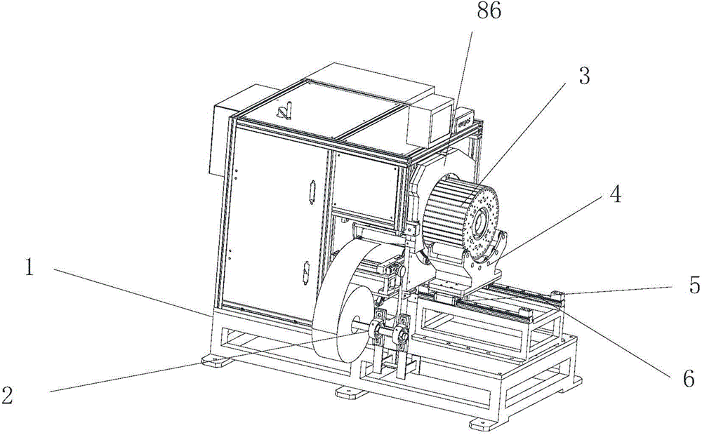
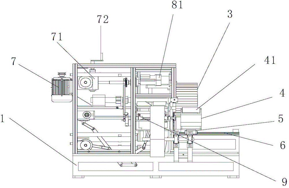
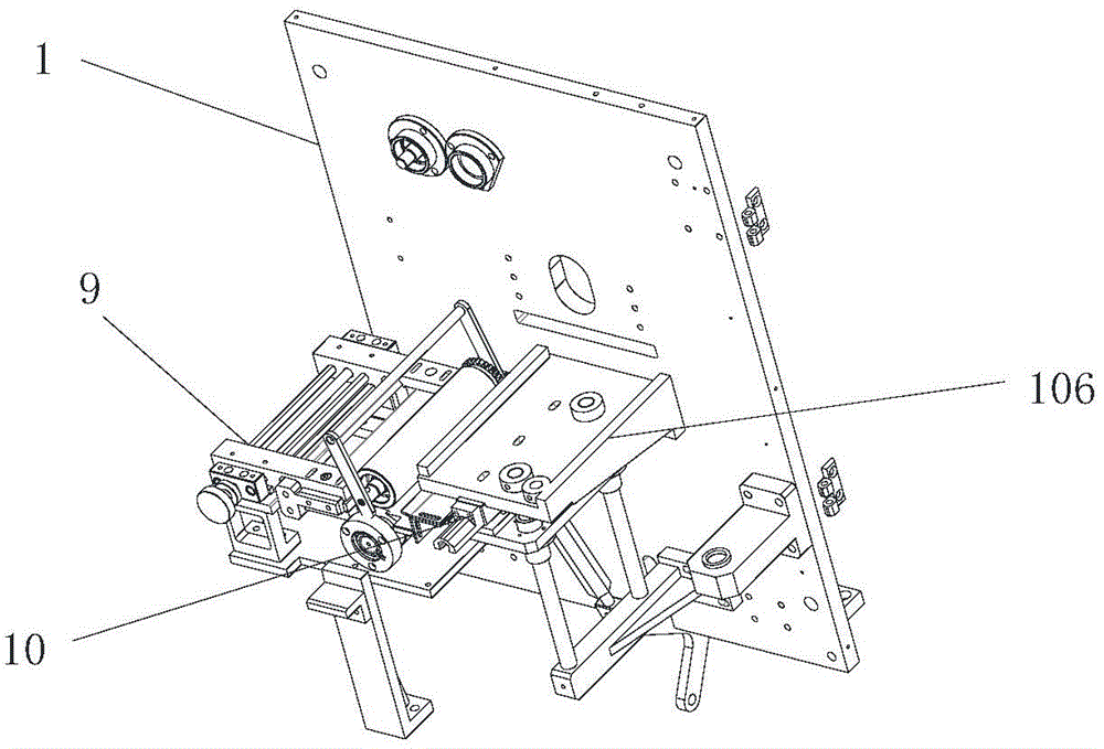
[0031] Such as Figure 1 to Figure 9The fan stator paper inserting machine shown includes a frame 1, a paper feeding mechanism 9 is arranged in the middle of the frame 1, and an insulating paper placement mechanism is arranged on the frame at the side of the paper feeding mechanism, and the insulating paper enters the paper feeding mechanism , the paper feeding mechanism folds the edges of the insulating paper, and sends the formed insulating paper into the forming mechanism. The paper feeding mechanism is a commonly used paper feeding mechanism in this field, so this application does not describe it in detail. The paper feeding mechanism 9 The frame at the end is provided with a forming mechanism, the frame on the right side of the forming mechanism is provided with an indexing mechanism, and the frame on the left side of the forming mechanism is provided with a drive...


PUM


Abstract

The invention belongs to the field of motor production equipment, specially relates to a paper inserting machine for a fan stator, and particularly relates to a paper inserting machine for a fan stator of which stator slots are arranged on the outer circumference of the stator. According to the paper inserting machine, a stator bearing mechanism is arranged on a frame on the right side of an indexing mechanism. According to the stator bearing mechanism, a guide rail is arranged on the frame, a sliding seat is arranged on the guide rail, the sliding seat is connected with a stator bearing seat, the upper part of the stator bearing seat is provided with an circular arc bearing concave cavity, and bearing rollers are evenly distributed in the bearing concave cavity along the axial direction. According to the invention, a fan stator paper inserting machine applicable to fan stator paper inserting is designed. The fan stator paper inserting machine has a stator bearing mechanism which can bear a fan stator without the need for hoisting or manual lifting operation, which, on one hand, offers protection to stator slots on the surface of the fan stator, and on the other hand, reduces the labor intensity of workers.

Description

technical field [0001] The invention belongs to the field of motor production equipment, and in particular relates to a paper-inserting machine for a fan stator, in particular to a stator-inserting machine for a fan stator with a stator slot located on the outer peripheral surface of the stator. Background technique [0002] Insulating paper is widely used in motor stators because of its excellent insulating properties and strong mechanical properties. Due to the particularity of its volume and structure, fan stators are particularly difficult to assemble on insulating paper. [0003] First of all, due to the large size and heavy weight of the fan stator, the bearing mechanism on the existing paper insertion machine cannot fix the fan stator, and special auxiliary fixtures need to be installed, which increases the investment in equipment. When fixing the fan stator, during the installation process, workers need to manually lift the stator for a long time, resulting in high ...

Claims


Application Information

Patent Timeline
Patent Type & Authority Applications(China)
IPC IPC(8): H02K15/10
Inventor 钟仁康舒会虎
Owner CHANGZHOU JINKANG PRECISION MECHANISM
Why Eureka
Try Eureka