Backlight circuit and backlight with same

A backlight circuit and current technology, which is applied in the field of backlight, can solve the problems of large power loss of LED light strings, and achieve the effects of reducing temperature, preventing excessive temperature, and reducing heat

Active Publication Date: 2014-11-19
HEFEI XINSHENG OPTOELECTRONICS TECH CO LTD +1
View PDF6 Cites 5 Cited by
  • Summary
  • Abstract
  • Description
  • Claims
  • Application Information

AI Technical Summary

Problems solved by technology

However, the premise of this method is that changes in the current flowing through a certain string of LED lights lead to changes in the brightness of the LED light strings, and no adjustment is made wh

Method used


Image

  • Backlight circuit and backlight with same
  • Backlight circuit and backlight with same
  • Backlight circuit and backlight with same

Examples


Example Embodiment

[0026] The specific embodiments of the present invention will be described in detail below with reference to the accompanying drawings. It should be understood that the specific embodiments described here are only used to illustrate and explain the present invention, and are not used to limit the present invention.

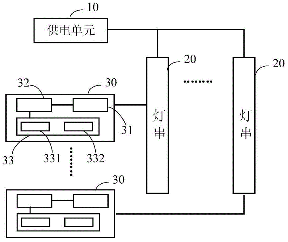
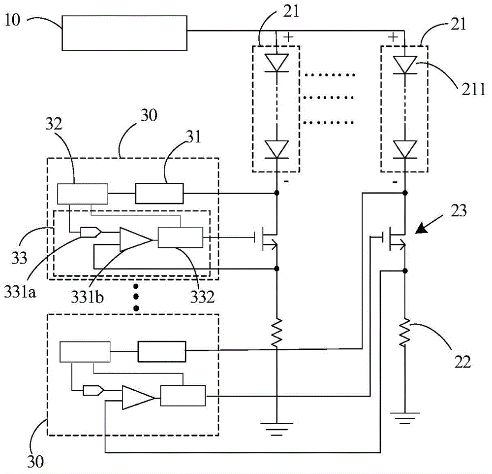
[0027] As an aspect of the present invention, such as figure 1 with figure 2 As shown, a backlight circuit is provided, which includes a power supply unit 10, a plurality of light strings 20, and a plurality of adjustment units 30 corresponding to the plurality of light strings 20, each light string 20 includes a series of light-emitting element groups 21 and feedback The resistor 22 and the adjusting unit 30 are used to adjust the current flowing through the light string 20 so that the potential of the negative terminal of each light-emitting element group 21 is not greater than the preset voltage value.

[0028] In the present invention, the current flowing through ...


PUM


Abstract

The invention provides a backlight circuit and a backlight with the same. The backlight circuit comprises a power supply unit and a plurality of lamp strings, and further comprises a plurality of adjusting units in one-one correspondence with the lamp strings, wherein each lamp string comprises a shining piece group and a feedback resistor which are connected in series; the adjusting units are used for adjusting currents flowing through the lamp strings, so that the electric potential at the cathode terminal of each shining piece group is not larger than a preset voltage value. The power consumption on each lamp string can be reduced, so as to lower the temperature of the backlight circuit.

Description

technical field [0001] The invention relates to the technical field of liquid crystal display, in particular to a backlight circuit and a backlight source including the backlight circuit. Background technique [0002] The backlight driving circuit of the display device includes a power supply, a driver chip and LED lamp strings. The power supply provides voltage, and the driver chip generates a pulse modulation signal (PWM), which can uniformly control the average current flowing through each string of lights. The power supply provides a uniform voltage. Since the voltage drop of each group of LED light strings is different, the current flowing through each LED light string can be kept constant by controlling the voltage drop on the switch tubes connected to the LED light strings. However, when the voltage drop of each LED light string has a large difference, the voltage drop on the corresponding switch tube is relatively large, resulting in a large power consumption of the ...

Claims


Application Information

Patent Timeline
IPC IPC(8): H05B37/02
Inventor 张大宇
Owner HEFEI XINSHENG OPTOELECTRONICS TECH CO LTD
Why Eureka
Try Eureka