
Apparatus for artificial ventilation having an absolute pressure sensor and a differential pressure sensor

A differential pressure sensor, pressure sensor technology, applied in the direction of respirator, etc., can solve the problems of reduced resolution, inability to measure pressure drop, inability to measure negative relative pressure, etc.

Inactive Publication Date: 2014-11-26
AIR LIQUIDE MEDICAL
View PDF7 Cites 6 Cited by
  • Summary
  • Abstract
  • Description
  • Claims
  • Application Information

AI Technical Summary

Problems solved by technology

Typically, however, differential pressure sensors on ventilators cannot measure negative relative pressures, at least not this type of pressure drop
One solution consists in using sensors designed to measure these types of pressure drops, but because their measurement range will be wider, their resolution will be reduced, resulting in compromised quality of pressure regulation

Method used


Image

  • Apparatus for artificial ventilation having an absolute pressure sensor and a differential pressure sensor
  • Apparatus for artificial ventilation having an absolute pressure sensor and a differential pressure sensor

Examples


Embodiment Construction

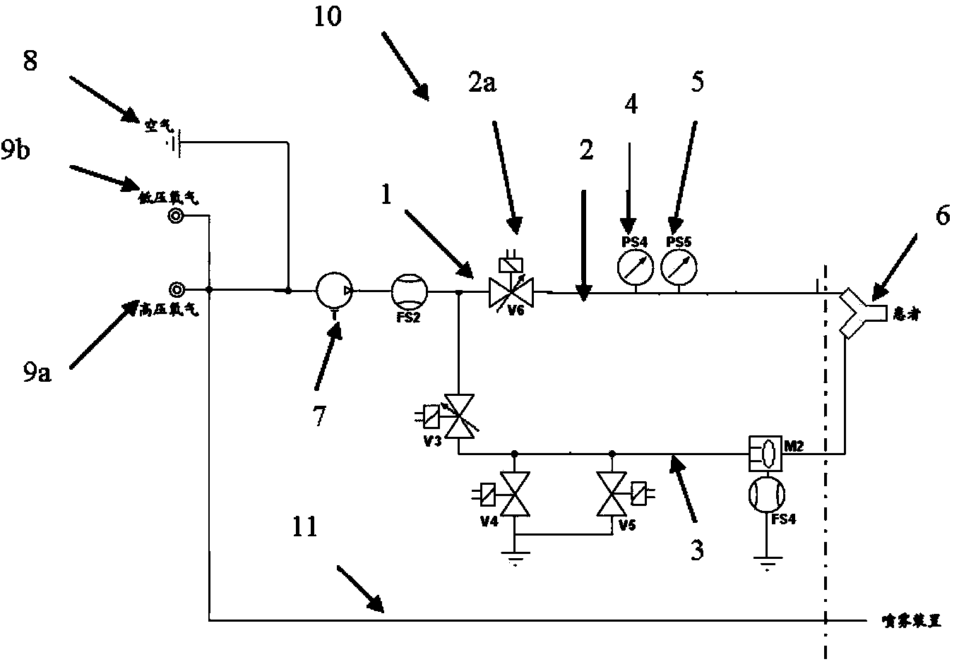
[0037] figure 1 A schematic diagram of an artificial respiration device according to the present invention or more simply a ventilator 10 is shown.

[0038] The ventilator 10 includes a patient circuit 1 with gas conduits that allow the gas to be administered to the patient to be supplied from one or more gas sources 8, 9a, 9b, or, conversely, to collect the gas exhaled by the patient.

[0039] The patient circuit 1 particularly includes an inhalation branch 2 and an exhalation branch 3 forming a loop. These inhalation branches 2 and exhalation branches 3 are connected to each other via a Y-shaped piece 6 located at the patient interface such as a mask, tracheal probe or any other device used to administer breathing gas to the patient. However, alternatively, the patient circuit 1 may include only one inhalation branch 2, that is, no exhalation branch.

[0040] According to the present invention, the differential pressure sensor 4 and the absolute pressure sensor 5 are located on th...


PUM


Abstract

This invention relates to an artificial breathing apparatus comprising a patient circuit (1) carrying gas comprising an inspiratory branch (2), and at least one pressure sensor arranged so as to operate at least one pressure measurement within the patient circuit (1), characterised in that it comprises a differential pressure sensor (4) and an absolute pressure sensor (5) located on the inspiratory branch (2), and control means cooperating with the differential pressure sensor (4) and the absolute pressure sensor (5) to detect a failure or malfunction of one or other of the said differential pressure (4) and absolute pressure sensor (5). The apparatus covered by the invention can be used in the treatment of chronic obstructive pulmonary disease (COPD), acute respiratory distress syndrome (ARDS) or in post-operative care.

Description

Technical field [0001] The invention relates to an artificial respiration device or device, which includes a redundant absolute pressure sensor and a differential pressure sensor in the inhalation branch of a patient circuit. Background technique [0002] Patients with respiratory failure, such as those suffering from chronic obstructive pulmonary disease (COPD), acute respiratory distress syndrome (ARDS), or those who need postoperative care and need to use respiratory assistance, that is, they need to use artificial respiration devices to supply breathing gas , Such as air, oxygen or oxygen-enriched air. [0003] In certain modes of operation, artificial respiration equipment or devices-commonly referred to as ventilators-regulate the pressure of breathing gas to be delivered to the patient. This adjustment is carried out by means of a pressure measuring device located in the inhalation branch of the ventilator. [0004] The failure of the measuring device may lead to incorrect a...

Claims


Application Information

Patent Timeline
IPC IPC(8): A61M16/00
CPCA61M16/0051A61M2016/0039A61M2016/0027A61M16/00A61M16/204A61M16/024
Inventor T·布兰格C·科林M·利巴尔迪
Owner AIR LIQUIDE MEDICAL
Learn More