
Photovoltaic greenhouse system structure

A system structure and photovoltaic technology, applied in the support structure of photovoltaic modules, photovoltaic modules, photovoltaic power generation, etc., can solve the problems of low labor efficiency, uncontrollable temperature, and labor-intensive, etc., and achieve high labor efficiency, low production cost, Set reasonable effects

Pending Publication Date: 2018-03-16
CHANGZHOU INST OF TECH
View PDF0 Cites 4 Cited by
  • Summary
  • Abstract
  • Description
  • Claims
  • Application Information

AI Technical Summary

Problems solved by technology

There are many advantages of greenhouse vegetable production, but there are also disadvantages. The support of the greenhouse currently used is covered with plastic film. Due to the poor light transmission of the plastic film, the photosynthesis of the plants in the greenhouse is insufficient, and the temperature in the greenhouse is uncontrollable. It is not conducive to the growth of plants controlled by temperature conditions, and does not have the management conditions for plant ventilation, fertilization, and irrigation. They are all managed manually. The management of batch greenhouse plants requires a lot of labor and low labor efficiency.

Method used


Image

  • Photovoltaic greenhouse system structure
  • Photovoltaic greenhouse system structure
  • Photovoltaic greenhouse system structure

Examples


Embodiment Construction

[0017] In order to more clearly illustrate the technical solutions in the embodiments of the present invention or the prior art, the following will briefly introduce the drawings that need to be used in the description of the embodiments or the prior art. Obviously, the accompanying drawings in the following description are only These are some embodiments of the present invention. For those skilled in the art, other drawings can also be obtained according to these drawings without any creative effort.

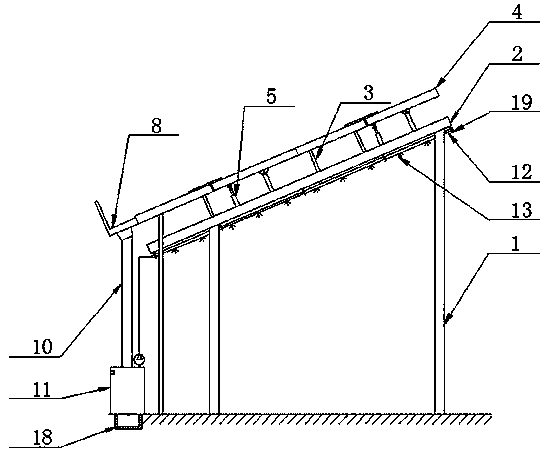
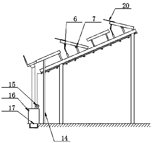
[0018] see as figure 1 —— image 3 As shown, this specific embodiment adopts the following technical scheme: it includes a support rod 1, a slanting rod 2, a bracket 3, a photovoltaic module 4, a cylinder 5, a connecting rod 6, a hinge 7, a drainage ditch 8, a drainage hole 9, a downpipe 10, Water tank 11, spray pipe 12, spray head 13, glass side plate 14, water pump 15; said support bar 1 is fixed with a slanting bar 2, and the slanting bar 2 is connected with several photovo...


PUM


Abstract

The invention relates to a photovoltaic greenhouse system structure, and relates to the technical field of planting greenhouses. An inclined rod is fixedly disposed on support rods and is connected with a plurality of photovoltaic modules via brackets and hinges, and cylinders are fixedly disposed on the inclined rod and are connected with the photovoltaic modules through connecting rods. The lower edge of the outermost photovoltaic module is connected with a drainage ditch, and drainage holes are uniformly distributed in the drainage ditch and are connected with a fall pipe which is connectedwith a water tank. A spray pipe is fixedly disposed below the inclined rod, spray headers are evenly distributed in the spray pipe, and the spray pipe is connected with the water tank through a waterpump. A glass side plate is connected below the outermost photovoltaic module, and the photovoltaic modules are connected with the cylinders and the water pump through circuits. According to the photovoltaic greenhouse system structure of the present invention, electricity is provided for a ventilation system and an irrigation system through photovoltaic power generation, artificial ventilation and irrigation are not needed, automatic collection and irrigation of rainwater are achieved, energy is saved, and labor efficiency is high.

Description

technical field [0001] The invention relates to the technical field of planting greenhouses, in particular to a photovoltaic greenhouse system structure. Background technique [0002] my country's solar energy resources are relatively abundant and widely distributed, and the development potential of solar photovoltaic power generation is huge. In addition, the current solar photovoltaic power generation technology has become increasingly mature, and it is one of the renewable energy technologies with ideal characteristics of sustainable development. At present, solar power generation devices are mostly installed on open land, resulting in a large amount of land resources being occupied. [0003] Traditional plastic film greenhouses can transmit light, keep warm (or heat), and are used to cultivate plants. In seasons that are not suitable for plant growth, it provides growth conditions for plant growth, can provide growth period and increase yield, and is mostly used for pla...

Claims


Application Information

Patent Timeline
Patent Type & Authority Applications(China)
IPC IPC(8): A01G9/14A01G9/24H02S20/30F24S25/00
CPCA01G9/14A01G9/1476A01G9/243A01G9/246A01G9/247H02S20/30Y02A40/25Y02E10/50Y02P60/12
Inventor 熊超陈磊朱锡芳李渊
Owner CHANGZHOU INST OF TECH
Learn More