
Printing device of thermosensitive and thermal-transfer-printing printer

A thermal transfer printer and printing device technology, applied in printing and other directions, can solve the problems of slow speed and only printing monochrome graphics and texts, and achieve the effects of improving printing quality, shortening heating time, and increasing moving speed

Active Publication Date: 2014-11-26
ZHEJIANG UNIV OF TECH
View PDF14 Cites 7 Cited by
  • Summary
  • Abstract
  • Description
  • Claims
  • Application Information

AI Technical Summary

Problems solved by technology

[0010] In order to solve the problems in the prior art that thermal and thermal transfer printing methods are slow and can only print monochrome graphics and texts, a printing device for thermal and thermal transfer printers is provided. This printing device has a reasonable structure and high printing speed. Fast, graphics and text printing that can be used in a variety of color levels

Method used


Image

  • Printing device of thermosensitive and thermal-transfer-printing printer
  • Printing device of thermosensitive and thermal-transfer-printing printer
  • Printing device of thermosensitive and thermal-transfer-printing printer

Examples


Embodiment 1

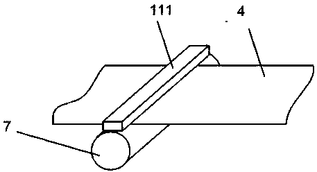
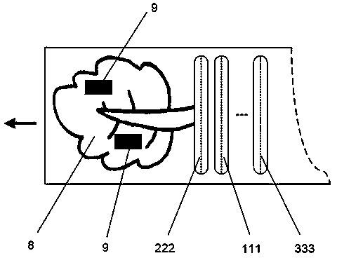
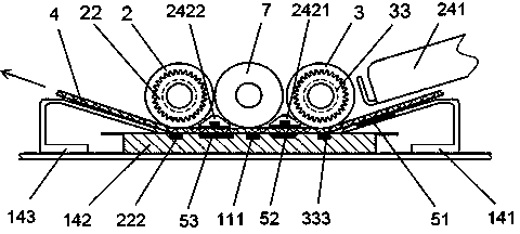
[0035] The printing device of a thermal printer. The print head consists of three parallel thermal print heads 111, 222, and 333. The three compression rubber rollers 2, 3, and 7 are mounted on the frame through bearings. The compression rubber roller will print The medium 4 is pressed against the print head; the pressing rubber roller is driven by a motor. The paper feeding ends of the three print heads are respectively provided with pre-heating zones 51, 52, 53. The pre-heating zones are installed on the paper guides 141, 142, and 143. The heating sheets used in the pre-heating zones are ceramic heating sheets.

[0036] The ceramic heating plate preheats the passing printing medium to an appropriate temperature and maintains a constant temperature. The temperature needs to be set according to the specific printing medium, which is generally higher than the ambient temperature but much lower than the temperature required for normal printing of the medium to increase the printing...

Embodiment 2

[0041] The difference from the first embodiment is that dual print heads are used in this embodiment. The print head is composed of two parallel thermal print heads 222 and 333. The print heads are respectively provided with pressing rubber rollers 2 and 3 to drive Gear 1 is connected to the drive motor, and the drive gear meshes with the outer ring gears of the two one-way bearing gears 22 and 33. The engagement directions of the inner and outer rings of the two one-way bearing gears are opposite. The compression rubber roller of the print head is fixedly connected.

[0042] Since the joining directions of the inner and outer rings of the two one-way bearings 22 and 33 are opposite, when the driving gear rotates counterclockwise, the outer ring of the second one-way bearing gear 22 on the left rotates clockwise, and the inner ring engages the follower; at this time, The outer ring of the first one-way bearing gear 33 on the right also rotates clockwise, and its inner ring is alw...

Embodiment 3

[0048] The difference from the second embodiment is that this embodiment is a printing device of a thermal transfer printer. There is a ribbon 6 passing between the printing medium 4 and the print head, and the ink on the ribbon is heated by the semiconductor printing head. On the printing medium 4, the printout is completed.


PUM


Abstract

Disclosed is a printing device of a thermosensitive and thermal-transfer-printing printer. Print heads include a plurality of thermosensitive print heads which are arrayed in parallel. Pressing rubber rolls are arranged at the print heads. The pressing rubber rollers are used for pressing a print medium which passes the print heads on the print heads tightly. The pressing rubber rolls are installed on a rack through bearings. The pressing rubber rolls are connected with a driving motor. Paper inlet ends of the print heads at paper guiding rails are provided with pre-heating areas. Each print point on the print medium is accumulatively completed through repeated printing of heating elements which belong to the print heads respectively so that heating time of each heating element is shortened and thus a movement speed, at which the print medium passes the printer, is improved and work efficiency of printing is improved and at the same time, pictures and text of gray level can be printed at the same time.

Description

Technical field [0001] The invention relates to a printing device of a thermal and thermal transfer printer. Background technique [0002] In thermal printers, a semiconductor heating element is installed on the print head. After the print head is heated and contacts the thermal paper, the required graphics and text can be printed. [0003] The core component of a thermal printer is the thermal print head. The thermal print head is equipped with dense, equidistant, linearly distributed semiconductor heating elements. The density of common heating elements is between 200-600 dots / inch. Each heating element can be independently controlled and instantly generate a high temperature above 200 ℃ . When the printer is working, the heating element of the thermal print head is close to the surface of the printing medium and moves in a direction that is not parallel to the straight line of the heating element distribution. [0004] The printing medium of the thermal printer may be thermal p...

Claims


Application Information

Patent Timeline
Patent Type & Authority Applications(China)
IPC IPC(8): B41J2/32B41J2/34
Inventor 胥芳占红武
Owner ZHEJIANG UNIV OF TECH
Learn More