A floating oil recovery device

An oil slick recovery and oil tank technology, which is applied in general water supply conservation, water conservancy projects, and open-air water surface cleaning, etc., can solve problems such as reducing oil return efficiency, and achieve the effect of high oil return efficiency.

Active Publication Date: 2015-11-18
ZHEJIANG OCEAN UNIV
View PDF4 Cites 1 Cited by
  • Summary
  • Abstract
  • Description
  • Claims
  • Application Information

AI Technical Summary

Problems solved by technology

However, there are some defects in this disclosed technology, because when the oil absorber absorbs oil, the liquid level is in a fluctuating state, and there is still a certain amount of air when the oil absorber sucks, thereby reducing the oil return efficiency

Method used


Image

  • A floating oil recovery device
  • A floating oil recovery device

Examples


Embodiment

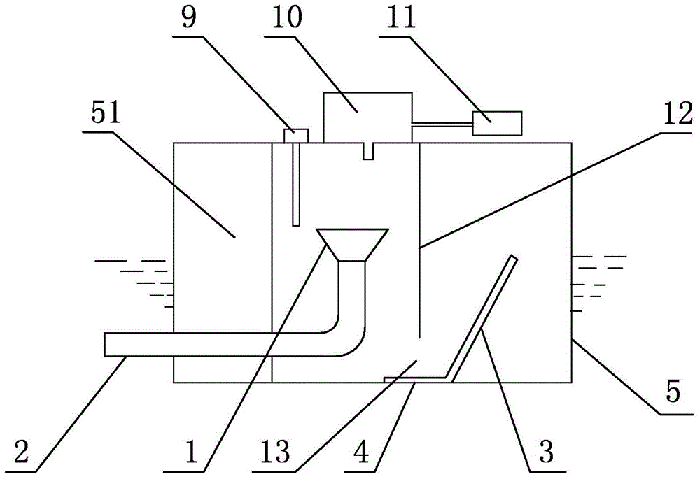
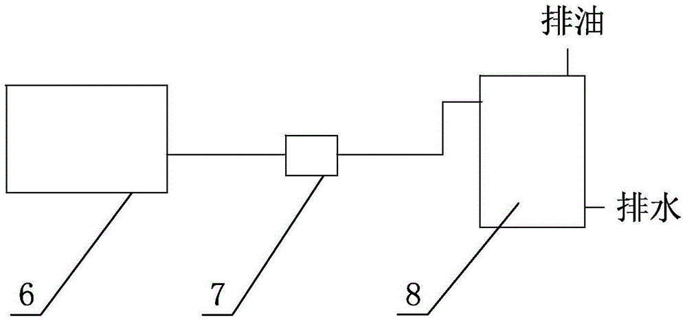
[0013] Embodiment: a kind of floating oil recovery device of the present invention, as attached figure 1 , attached figure 2 As shown, it includes an oil absorber 6, a pump 7, an oil-water separator 8, and the oil absorber 6 includes a floating oil tank 5, an inclined baffle plate 3, a bottom plate 4, an oil suction pan 1, an oil suction pipe 2, and a control system.

[0014] A partition 12 is arranged in the floating oil tank 5; the top and side of the partition 12 are all connected with the floating oil tank 5, and the channel opening 13 for oil liquid entry is arranged between the bottom end and the bottom of the floating oil tank 5, and the channel opening 13 lower than the top of the slanted baffle 3, the top of the slanted baffle 3 is lower than the suction port of the oil suction pan 1; On the side, the vacuum box 10 communicates with the floating oil tank 5. Under the action of vacuum, the oil return liquid level in the cavity where the oil suction plate is located ...


PUM


Abstract

The invention relates to a floating oil recovery device. The floating oil recovery device comprises an oil suction unit, a pump and an oil-water separator. The oil suction unit comprises a floating oil tank, an inclined baffle, a bottom plate, an oil suction disk, an oil suction pipe and a control system. A partition plate is arranged in the floating oil tank. The top and the sides of the partition plate are all connected with the tank body of the floating oil tank, a channel opening for oil to enter is arranged between the bottom end of the partition plate and the bottom of the tank body of the floating oil tank, the channel opening is lower than the top end of the inclined baffle, and the top end of the inclined baffle is lower than a suction opening of the oil suction disk. A vacuum chamber and a vacuum pump are arranged on the upper portion of the floating oil tank, and the vacuum chamber and the inclined baffle are arranged on the two sides of the partition plate respectively, and communicated with the floating tank. Due to the structure, under the vacuum action, the return oil liquid level in a cavity where the oil suction disk is located is higher than the liquid level on one side of the inclined baffle, the height difference between the return oil liquid level and the suction opening of the oil suction disk can be controlled through the vacuum degree so as to be kept within a certain range, and thus the suction opening of the oil suction disk is kept immersed below the return oil liquid level, air is effectively prevented from being sucked in, and the oil return efficiency is prevented from being reduced.

Description

technical field [0001] The invention relates to oil slick treatment, in particular to an oil slick recovery device. Background technique [0002] Due to offshore operation facilities (offshore oil drilling platforms, production platforms, etc.), oil transport ships, and oil transshipment terminals during normal operations (drilling and oil testing) and accidents, a large amount of oil products will flow into the ocean, waters, and port water surface, resulting in The loss of oil resources and the destruction of the environment, some inventors proposed a public technology called "oil floating recovery device" (authorized announcement number: CN2041302U), the public technology is composed of oil absorber, pump and oil-water separator, etc. The oil suction plate with upward suction port and the buoyant buoyancy tank bring in less air when the floating oil is sucked in, which shortens the oil collection time and improves the oil collection efficiency. Because of the oil-water se...

Claims


Application Information

Patent Timeline
Patent Type & Authority Patents(China)
IPC IPC(8): E02B15/10
CPCY02A20/204
Inventor 孙静亚孙会玲
Owner ZHEJIANG OCEAN UNIV
Why Eureka
Try Eureka