
Grease backflow device of annular isolation-type respirator

An isolated, lubricating oil technology, applied in the direction of machines/engines, engine components, mechanical equipment, etc., can solve the problems of reducing the effect of separating lubricating oil of respirator, increasing lubricating oil discharge and fuel consumption, etc., to reduce lubricating oil consumption, The effect of improving the recovery rate and improving the utilization rate

Inactive Publication Date: 2014-11-26
NO 711 RES INST CHINA SHIPPING HEAVY IND GRP
View PDF12 Cites 0 Cited by
  • Summary
  • Abstract
  • Description
  • Claims
  • Application Information

AI Technical Summary

Problems solved by technology

However, due to the pressure difference between the crankcase and the outlet of the breather, the oil mist flow inside the crankcase will continue to enter the air intake pipe of the breather. Oil is blown into the breather, which reduces the effectiveness of the breather in separating oil, increasing oil emissions and fuel consumption

Method used


Image

  • Grease backflow device of annular isolation-type respirator
  • Grease backflow device of annular isolation-type respirator

Examples


Embodiment Construction

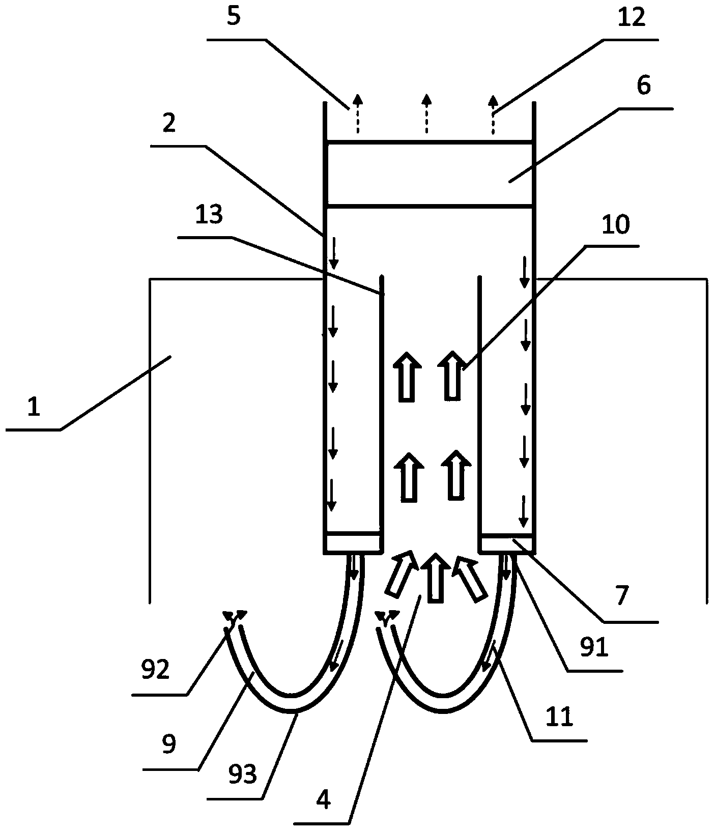
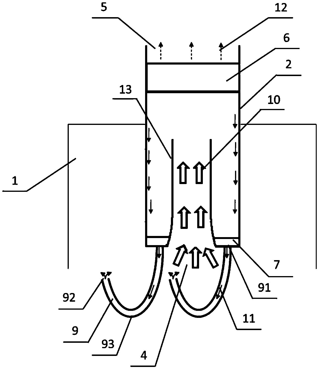
[0023] Such as figure 1 As shown, a preferred embodiment of the present invention provides an annular isolated respirator lubricating oil return device, and its structure specifically includes an oil-gas separation part 6, a lubricating oil recovery part 7, a lubricating oil return part 9 and an airflow guide part 13. The oil-gas separation component 6 is set at the air outlet 5 on the top of the respirator 2 . The gas guiding part 13 is cylindrical, one end communicates with the air inlet 4 arranged at the bottom of the respirator, and the other end opens toward the oil-gas separating part 6 . In another embodiment of the present invention, as figure 2 As shown, the gas guide member 13 is set such that the opening at one end is larger than the opening at the other end, and the end with the larger opening communicates with the air inlet. This shape of the gas guide member 13 is more conducive to the entry of oil mist with lubricating oil.

[0024] Such as figure 1 and fi...


PUM


Abstract

The invention discloses a grease backflow device of an annular isolation-type respirator. The grease backflow device specially and structurally comprises a grease and air separating part, grease recovery parts, grease backflow parts and air flow guide parts. The grease and air separating part is arranged at the position of an air outlet in the top of the respirator, the air guide parts are communicated with an air inlet formed in the bottom of the respirator, the grease recovery parts are arranged at the bottom of the respirator and surround the air guide parts and the grease backflow pars are communicated with the grease recovery parts.

Description

technical field [0001] The invention relates to a lubricating oil backflow device, in particular to a lubricating oil backflow device for an annular isolated respirator, which belongs to the technical field of marine diesel engines. Background technique [0002] When the engine is running normally, the gas pressure in the crankcase will continue to rise and fluctuate, and a breather is usually used to slow down and reduce the pressure in the crankcase. The respirator is generally equipped with an oil-air separation device to filter most of the lubricating oil in the exhaust airflow of the crankcase, and the filtered lubricating oil is returned to the crankcase, thereby reducing the oil consumption of the lubricating oil. [0003] The engines of marine diesel engines generally use a normally open breather, which allows the separated oil to flow directly back to the crankcase. However, due to the pressure difference between the crankcase and the outlet of the respirator, the ...

Claims


Application Information

Patent Timeline
IPC IPC(8): F01M13/04
Inventor 张延亭陈志忠李新才鄢岚李丽婷姜久奎
Owner NO 711 RES INST CHINA SHIPPING HEAVY IND GRP
Learn More